TDA4VM: Inquiry about the issue of lights turning purple

Part Number: TDA4VM

Tool/software:

Hi Gang,

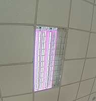
Regarding the issue where the lamp appears purple, I have created a new thread, and we can discuss it here.

First of all, how can I tell if it's an ISP issue or a driver issue? 

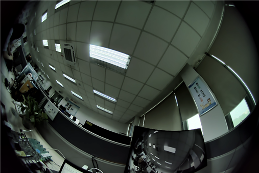
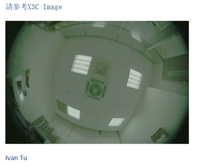
1. I asked colleagues from the camera module manufacturing department for the pictures of X3C being activated with other tools at that time. As shown in the figure, without software driver or ISP processing, the lamp appears white, which can prove that the camera module is in good condition.

2. I used the software driver and GStreamer command to save the raw image without ISP processing, and the lamp appears white.

gst-launch-1.0 -v v4l2src num-buffers=1 device=/dev/video-ox03c10-cam0 io-mode=dmabuf ! video/x-bayer, width=1920, height=1280, framerate=30/1, format=bggr12 ! multifilesink location="image-%d.raw"

Therefore, I suspect the issue is on the ISP side. What do you think I should do to find the cause?
Thanks!
  • Hi Gang,

    1.After multiple tests, I've found that this seems to be an issue with the WDR decomposition extension. As shown in the figure below, if I remove the last 4 pairs of coordinates, both the indoor tone and the color of the lamps are normal. However, when these coordinates are added back, the entire indoor area, including the lamps, turns purple. How should I resolve this problem?

    2. I tried modifying the content in algos/ae/src/TI_aaa_ae.c. How should I compile it to make the changes take effect?

  • Hi Ying,

    As shown in the figure, without software driver or ISP processing, the lamp appears white, which can prove that the camera module is in good condition.

    Yes, this raw image looks good.

    If you feed it into ISP with proper ISP settings, the output image should look good.

    I used the gstreamer pipeline below for old SDK version.

    gst-launch-1.0 multifilesrc stop-index=0 location=/opt/edgeai-test-data/raw_images/modules_test/imx390_raw_image_1936x1096_16bpp_exp0.raw caps="video/x-bayer, width=1936, height=1096, format=rggb16" ! tiovxisp sensor-name=SENSOR_SONY_IMX390_UB953_D3 dcc-isp-file=/opt/imaging/imx390/wdr/dcc_viss_wdr.bin format-msb=11 sink_0::dcc-2a-file=/opt/imaging/imx390/wdr/dcc_2a_wdr.bin ! filesink location=output_imx390.yuv

    For latest SDK, you may need to add "wdr-enabled=true".

    https://e2e.ti.com/support/processors-group/processors/f/processors-forum/1535185/am62a7-awb-is-not-effective/5960218?tisearch=e2e-sitesearch&keymatch=wdr_enabled#

    I suspect the issue is on the ISP side. What do you think I should do to find the cause?

    Output color could go wrong at runtime if AWB gains get wrong or some wrong register values are sent to sensor.

    You may start with static images first for testing.

  • How should I compile it to make the changes take effect?

    These changes will get into the DCC binary file for gstreamer pipeline.

    Please refer to the app note for details.

    https://www.ti.com/lit/pdf/sprad86

  • Hi Gang,

    You may start with static images first for testing.

    After testing, the static images are fine, and the lamps are white. The static images have a green tint, while the dynamic images have a purple tint.

    Output color could go wrong at runtime if AWB gains get wrong or some wrong register values are sent to sensor.
    Next, how should I check whether the problem is with AWB or the registers?
    Thanks!

    static images.rar

  • Hi Gang,

    Can you help me take a look at this problem? Thank you very much.
  • Hi Ying,

    After testing, the static images are fine, and the lamps are white. The static images have a green tint,

    Is the static case fine or with a green tint?

    Next, how should I check whether the problem is with AWB or the registers?

    You may check if AWB output gains are stable in your environment.

  • Hi Gang,

    Is the static case fine or with a green tint?

    It's fine.

    You may check if AWB output gains are stable in your environmen

    If static images are fine, then my next step is to check the AWB output gains. Could you please tell me how to check this?

  • Hi Ying,

    If static images are fine, then my next step is to check the AWB output gains. Could you please tell me how to check this?

    You may print out the AWB gains and check if there are any abnormal values.

  • Hi Gang,

    I understand what you mean. Are you saying that I can print AWB gains in the ‘imaging’ source code? However, if I modify the code, how should I compile it to make the changes take effect? I am using the TDA4VM-EVM,  Linux EdgeAI version,  But I haven't found an SDK that can build the 2A algorithm like the one for AM62A.

  • Hi Ying,

    Are you using SK-TDA4VM?

    https://www.ti.com/tool/SK-TDA4VM

  • Hi,

     I am using the TDA4VM-EVM,  Linux EdgeAI version

    No, I am not using the SK-TDA4VM. I am using the TDA4VM-EVM. Could you please help me find the link? Thank you.

  • Hi Ying,

    I am using the TDA4VM-EVM. Could you please help me find the link?

    I am not aware of any edgeai SDK support for TDA4VM-EVM.
    As far as I know, edgeai is only supported on SK boards.

    Copying  for his comments.

  • Hi,

    1. I am using the TDA4VM-EVM. I don't mean to get stuck on whether I can download the EdgeAI SDK.

    2. My ultimate request is: I have modified imaging/algos/ae/src/TI_aaa_ae.c, and I want to know how to compile it so that the modification takes effect on the board. Could you understand my need?

    3. I have found the document "How to modify and rebuild TI's 2A algorithm for AM6xA Processor SDK Linux", but it isn't applicable to TDA4VM-EVM.

  • Hi Ying,

    My ultimate request is: I have modified imaging/algos/ae/src/TI_aaa_ae.c, and I want to know how to compile it so that the modification takes effect on the board. Could you understand my need?

    TDA4VM-EVM works with the RTOS version of SDK and there no extra step needed for rebuilding AE.

    https://www.ti.com/tool/PROCESSOR-SDK-J721E

    I have found the document "How to modify and rebuild TI's 2A algorithm for AM6xA Processor SDK Linux"

    That is only needed for SK boards.

  • Hi Gang,

    Could you please help confirm whether my current development board can flash the EdgeAI SDK? If it can, do I need to reinstall the RTOS SDK to build the 2A algorithm? Thank you.

  • Hi Ying,

    Could you please help confirm whether my current development board can flash the EdgeAI SDK?

    TDA4VM-EVM is not supported by EdgeAI SDK.

    Please follow the instruction under "Supported products & hardware" on the SDK page.

    https://www.ti.com/tool/PROCESSOR-SDK-J721E

  • Hi Gang,

    I understand the issues with the SDK and the purple blank frames, and I have resolved them. Now, let's go back to the problem of the lights having a purple tint.

    1. I printed out the AWB gains, and they seem to be normal. Could you please help me check it? Thank you.

    rY=77, gY=150, bY=29
    AE debug: R = 81, G = 117, B = 77
    AE debug: curY=102, avgY=101, locked=0, lockcnt=0
    AE debug: dec Tmin=100, Tmax=65535, Tstep=1
    AE debug: i=0, r=0, num=1
    AE debug: cA, cT, cAG, cDG = 1, 100, 1024, 256
    AE debug: nA, nT, nAG, nDG = 1, 100, 1024, 256, r=0
    WB gains: r_gain=256, g_gain=256, b_gain=256
    rY=77, gY=150, bY=29
    AE debug: R = 81, G = 118, B = 78
    AE debug: curY=102, avgY=101, locked=0, lockcnt=0
    AE debug: dec Tmin=100, Tmax=65535, Tstep=1
    AE debug: i=0, r=0, num=1
    AE debug: cA, cT, cAG, cDG = 1, 100, 1024, 256
    AE debug: nA, nT, nAG, nDG = 1, 100, 1024, 256, r=0
    WB gains: r_gain=256, g_gain=256, b_gain=256

    2. Could it be due to WDR compression? How should I troubleshoot whether it is caused by WDR?

  • Hi Gang,

    I haven't received your reply in the past few days. I hope you can help me look into my issue when you have time. Thank you very much.

  • Hi Ying,

    I haven't received your reply in the past few days. I hope you can help me look into my issue when you have time. Thank you very much.

    I am out of office intermittently and delay in my response is expected.

    I understand the issues with the SDK and the purple blank frames, and I have resolved them.

    What was the cause of this problem?

    I have not seen any similar issue previously in our SDK S/W.
    Everything should just work out of box.

    1. I printed out the AWB gains, and they seem to be normal. Could you please help me check it? Thank you.
    2. Could it be due to WDR compression? How should I troubleshoot whether it is caused by WDR?

    I cannot tell if AWB is working in your system.
    All the AWB gains printed are all 256, which is not typical.

    I did not see any companding issue in your previously shared raw images and xml files.
    You might have missed something in your workflow.
    Typically, AWB would just work after calibration is done in tuning tool, unless the lighting condition is out of calibration.

  • Hi Gang,

    1. The previous logs were printed in ‘TI_aaa_ae.c’ and are not very accurate. The following logs are printed in ‘ti_2a_wrapper/src/ti_2a_wrapper.c’. Could you please take another look for me?

    gst-launch-1.0 v4l2src device=/dev/video-ox03c10-cam0 io-mode=dmabuf-import ! video/x-bayer, width=1920, height=1280, format=bggr12 ! tiovxisp sink_0::device=/dev/v4l-ox03c10-subdev0 sensor-name=SENSOR_SONY_OX03C10_UB953_D3 dcc-isp-file=/opt/imaging/ox03c10/wdr/dcc_viss_wdr.bin ee_mode=EE_MODE_Y8  wdr-enabled=true sink_0::dcc-2a-file=/opt/imaging/ox03c10/wdr/dcc_2a_wdr.bin format-msb=11 ! video/x-raw, format=NV12, width=1920, height=1280 ! kmssink driver-name=tidss sync=false
    APP: Init ... !!!
    MEM: Init ... !!!
    MEM: Initialized DMA HEAP (fd=6) !!!
    MEM: Init ... Done !!!
    IPC: Init ... !!!
    IPC: Init ... Done !!!
    REMOTE_SERVICE: Init ... !!!
    REMOTE_SERVICE: Init ... Done !!!
       370.528389 s: GTC Frequency = 200 MHz
    APP: Init ... Done !!!
       370.528451 s:  VX_ZONE_INIT:Enabled
       370.528458 s:  VX_ZONE_ERROR:Enabled
       370.528464 s:  VX_ZONE_WARNING:Enabled
       370.529259 s:  VX_ZONE_INIT:[tivxPlatformCreateTargetId:116] Added target MPU-0
       370.529362 s:  VX_ZONE_INIT:[tivxPlatformCreateTargetId:116] Added target MPU-1
       370.529446 s:  VX_ZONE_INIT:[tivxPlatformCreateTargetId:116] Added target MPU-2
       370.529520 s:  VX_ZONE_INIT:[tivxPlatformCreateTargetId:116] Added target MPU-3
       370.529528 s:  VX_ZONE_INIT:[tivxInitLocal:136] Initialization Done !!!
       370.529982 s:  VX_ZONE_INIT:[tivxHostInitLocal:101] Initialization Done for HOST !!!
    Setting pipeline to PAUSED ...
    Pipeline is live and does not need PREROLL ...
    Pipeline is PREROLLED ...
    Setting pipeline to PLAYING ...
    New clock: GstSystemClock
    [  364.526464] EXPOSURE reg value:00 64
    [  364.531058] AGAIN reg value:08 00
    [  364.536032] DGAIN reg value:03 40 00
    
       371.053515 s:  VX_ZONE_ERROR:[TI_2A_wrapper_create:126] DCC ID = 233
       371.053528 s:  VX_ZONE_ERROR:[TI_2A_wrapper_create:127] Image Format = 0
       371.053534 s:  VX_ZONE_ERROR:[TI_2A_wrapper_create:128] Phase = 0
       371.053540 s:  VX_ZONE_ERROR:[TI_2A_wrapper_create:129] awb_mode = 0
       371.053546 s:  VX_ZONE_ERROR:[TI_2A_wrapper_create:130] ae_mode = 0
       371.053551 s:  VX_ZONE_ERROR:[TI_2A_wrapper_create:131] awb_num_skip_frames = 0
       371.053557 s:  VX_ZONE_ERROR:[TI_2A_wrapper_create:132] ae_num_skip_frames = 0
       371.053643 s:  VX_ZONE_ERROR:[TI_2A_wrapper_create:164] Before dcc_update : awb_calb_data.radius = 0x32
       371.053702 s:  VX_ZONE_ERROR:[TI_2A_wrapper_create:[  364.651011] AGAIN reg value:01 00
    180] After dcc_update : awb_calb_data.radius = 0x32
       371.053873 s:  VX_ZONE_ERROR:[TI_2A_wrapper_create:261] DCC succeeded
       371.053912 s:  VX_ZONE_ERROR:[TI_2A_wrapper_create:274] AWB Initialization successful
       371.053945 s:  VX_ZONE_ERROR:[TI_2A_wrapper_create:292] AWB_ScratchMemory size = 10579
    IttCtrl_registerHandler: command echo registered at location 0
    IttCtrl_registerHandler: command iss_read_2a_params registered at location 1
    IttCtrl_registerHandler: command iss_write_2a_params registered at location 2
    IttCtrl_registerHandler: command iss_raw_save registered at location 3
    IttCtrl_registerHandler: command iss_yuv_save registered at location 4
    IttCtrl_registerHandler: command iss_read_sensor_reg registered at location 5
    IttCtrl_registerHandler: command iss_write_sensor_reg registered at location 6
    IttCtrl_registerHandler: command dev_ctrl registered at location 7
    IttCtrl_registerHandler: command iss_send_dcc_file registered at location 8
    Error: failed to open i2c bus at /dev/i2c-9
    Warning: Failed to initialize i2c bus. Register read/write will not work !!!
     NETWORK: Opened at IP Addr = 192.168.10.99, socket port=5000!!!
    Redistribute latency...
       371.112096 s:  VX_ZONE_ERROR:[decode_h3a_header_dcc:658] decode_h3a_header_dcc : num_rows = 16
       371.112115 s:  VX_ZONE_ERROR:[decode_h3a_header_dcc:659] decode_h3a_header_dcc : num_cols = 32
       371.112122 s:  VX_ZONE_ERROR:[decode_h3a_header_dcc:660] decode_h3a_header_dcc : num_pix = 80
       371.112128 s:  VX_ZONE_ERROR:[AWB_TI_parse_H3a_buf:834] H3A color: r=3, gr=2, gb=1, b=0
    rY=77, gY=150, bY=29
    AWB raw gains - R: 515, Gr: 256, Gb: 256, B: 439
    Mapped WB gains - R[3]: 1024, Gr[2]: 512, Gb[1]: 512, B[0]: 878
    AWB Gain = (670, 512, 512, 724)
    Saved Ctrl gains - R: 724, G: 512, B: 670
       465.795667 s:  VX_ZONE_ERROR:[decode_h3a_header_dcc:658] decode_h3a_header_dcc : num_rows = 16
       465.795707 s:  VX_ZONE_ERROR:[decode_h3a_header_dcc:659] decode_h3a_header_dcc : num_cols = 32
       465.795714 s:  VX_ZONE_ERROR:[decode_h3a_header_dcc:660] decode_h3a_header_dcc : num_pix = 80
       465.795720 s:  VX_ZONE_ERROR:[AWB_TI_parse_H3a_buf:834] H3A color: r=3, gr=2, gb=1, b=0
    awbStatus:0
    AWB raw gains - R: 508, Gr: 256, Gb: 256, B: 435
    Mapped WB gains - R[3]: 1022, Gr[2]: 512, Gb[1]: 512, B[0]: 876
    AWB Gain = (670, 512, 512, 723)
    Saved Ctrl gains - R: 723, G: 512, B: 670
       465.861696 s:  VX_ZONE_ERROR:[decode_h3a_header_dcc:658] decode_h3a_header_dcc : num_rows = 16
       465.861738 s:  VX_ZONE_ERROR:[decode_h3a_header_dcc:659] decode_h3a_header_dcc : num_cols = 32
       465.861744 s:  VX_ZONE_ERROR:[decode_h3a_header_dcc:660] decode_h3a_header_dcc : num_pix = 80
       465.861751 s:  VX_ZONE_ERROR:[AWB_TI_parse_H3a_buf:834] H3A color: r=3, gr=2, gb=1, b=0
    awbStatus:0
    AWB raw gains - R: 508, Gr: 256, Gb: 256, B: 437
    Mapped WB gains - R[3]: 1022, Gr[2]: 512, Gb[1]: 512, B[0]: 876
    AWB Gain = (670, 512, 512, 723)
    Saved Ctrl gains - R: 723, G: 512, B: 670
       465.927623 s:  VX_ZONE_ERROR:[decode_h3a_header_dcc:658] decode_h3a_header_dcc : num_rows = 16
       465.927661 s:  VX_ZONE_ERROR:[decode_h3a_header_dcc:659] decode_h3a_header_dcc : num_cols = 32
       465.927668 s:  VX_ZONE_ERROR:[decode_h3a_header_dcc:660] decode_h3a_header_dcc : num_pix = 80
       465.927674 s:  VX_ZONE_ERROR:[AWB_TI_parse_H3a_buf:834] H3A color: r=3, gr=2, gb=1, b=0
    rY=77, gY=150, bY=29
    awbStatus:0
    AWB raw gains - R: 509, Gr: 256, Gb: 256, B: 436
    Mapped WB gains - R[3]: 1022, Gr[2]: 512, Gb[1]: 512, B[0]: 876
    AWB Gain = (670, 512, 512, 723)
    Saved Ctrl gains - R: 723, G: 512, B: 670
       465.993569 s:  VX_ZONE_ERROR:[decode_h3a_header_dcc:658] decode_h3a_header_dcc : num_rows = 16
       465.993610 s:  VX_ZONE_ERROR:[decode_h3a_header_dcc:659] decode_h3a_header_dcc : num_cols = 32
       465.993617 s:  VX_ZONE_ERROR:[decode_h3a_header_dcc:660] decode_h3a_header_dcc : num_pix = 80
       465.993624 s:  VX_ZONE_ERROR:[AWB_TI_parse_H3a_buf:834] H3A color: r=3, gr=2, gb=1, b=0
    awbStatus:0
    AWB raw gains - R: 510, Gr: 256, Gb: 256, B: 436
    Mapped WB gains - R[3]: 1022, Gr[2]: 512, Gb[1]: 512, B[0]: 876
    AWB Gain = (670, 512, 512, 723)
    Saved Ctrl gains - R: 723, G: 512, B: 670
       466.059538 s:  VX_ZONE_ERROR:[decode_h3a_header_dcc:658] decode_h3a_header_dcc : num_rows = 16
       466.059579 s:  VX_ZONE_ERROR:[decode_h3a_header_dcc:659] decode_h3a_header_dcc : num_cols = 32
       466.059586 s:  VX_ZONE_ERROR:[decode_h3a_header_dcc:660] decode_h3a_header_dcc : num_pix = 80
       466.059592 s:  VX_ZONE_ERROR:[AWB_TI_parse_H3a_buf:834] H3A color: r=3, gr=2, gb=1, b=0
    awbStatus:0
    AWB raw gains - R: 511, Gr: 256, Gb: 256, B: 436
    Mapped WB gains - R[3]: 1022, Gr[2]: 512, Gb[1]: 512, B[0]: 876
    AWB Gain = (670, 512, 512, 723)
    Saved Ctrl gains - R: 723, G: 512, B: 670
       466.125592 s:  VX_ZONE_ERROR:[decode_h3a_header_dcc:658] decode_h3a_header_dcc : num_rows = 16
       466.125629 s:  VX_ZONE_ERROR:[decode_h3a_header_dcc:659] decode_h3a_header_dcc : num_cols = 32
       466.125635 s:  VX_ZONE_ERROR:[decode_h3a_header_dcc:660] decode_h3a_header_dcc : num_pix = 80
       466.125641 s:  VX_ZONE_ERROR:[AWB_TI_parse_H3a_buf:834] H3A color: r=3, gr=2, gb=1, b=0
    rY=77, gY=150, bY=29

    2. Additionally, my AWB is functioning properly, as I can observe its effects.

    I understand the issues with the SDK and the purple blank frames, and I have resolved them.

    3. This is because there is an issue with the setting of the minimum exposure value in 2A.

  • Hi Ying,

    The following logs are printed in ‘ti_2a_wrapper/src/ti_2a_wrapper.c’.

    Are you still using edgeai?
    I thought you switched to RTOS.

    Could you please take another look for me?

    These gain values look consistent to me.

    Additionally, my AWB is functioning properly, as I can observe its effects.

    Thanks for the update!

    This is because there is an issue with the setting of the minimum exposure value in 2A.

    Ok, that may result in wrong sensor register values.

    Please follow these FAQ for setting up AE.

     [FAQ] Setting up Auto Exposure (AE) for your image sensor with TDA4/AM6xA ISP (VPAC) 

     [FAQ] AM62A7: How to Set the Minimum/Maximum Exposure Time and Analog Gain for 2A Algorithm? 

     [FAQ] AM62A7: How to modify and rebuild TI's 2A algorithm for AM6xA Processor SDK Linux? 

  • Hi Gang,

    So, is there a problem with my AWB gains?  Is the purplish light caused by this reason?

    Additionally, I will first organize my current questions into a document. I will ask Hsu, James to forward it to you. Please take a look and see if it is necessary to communicate via a call or if we should continue communicating on the e2e forum. Thank you for your help

  • Hi Ying,

    Thanks for sharing the summary!

    So, is there a problem with my AWB gains?  Is the purplish light caused by this reason?

    If the color tint is global, then it is typically an AWB calibration issues.
    If you see most gray objects in the view are white balanced, that is typically not a problem of AWB itself.

    Local purple color around lights is typically an issue in the sensor especially when there is motion (i.e., you may only see purple color with motion).
    While the sensor internally merges multiple exposure frames together, it may create purple color artifacts especially with motion.
    Some OVT sensors may require using AWB gains in the sensor avoid those purple artifacts.
    You may check with OVT for details.

    Purple color similar to below is typically the sensor issue (or due to wrong WDR companding knee points used in ISP).
    AWB is working properly as the ceiling is white balanced correctly.

    H3A_INPUT_LSB affects both AE and AWB, but it is easy to tell if AWB is working properly (or we may simply use fixed AWB gains).
    If sensor exposure changes while you change H3A_INPUT_LSB, then purple color may look different because in-sensor HDR merge becomes different.

  • Regarding your question about controlling X3C exposure, you would have to add your own code for writing to corresponding X3C registers.
    For example, at the link below, IMX390 registers are modified in sensor driver.
    https://git.ti.com/cgit/processor-sdk/imaging/tree/sensor_drv/src/imx390/iss_sensor_imx390.c?h=main#n503

    TI's reference AE code in SDK only controls exposure time and gain.
    You would need to map those to your sensor register settings in sensor driver according to X3C manual and OVT's support.

  • About NSF4 tuning, you may follow the tuning tool plugin guide.

    1. sensor noise distribution varies with sensor gain (and AWB gains if they are applied before NSF4).

    You may have to tune NSF4 separately while noise distribution changes.

    2/3. At each sensor gain level, you would need to get noise level at various pixel brightness level for WDR sensors.

    That requires bright and dark lighting scenes and multiple raw images to be captured and used together so that most of the 16-bit X range is covered.

    4. Noise filtering is a trade-off between removing noise and keeping details.
    It is not possible to only remove noise while keep all the details.

  • Hi Gang,

    Thank you for your reply and help the other day. I have summarized the following questions:

    1. When there is no movement, the lights and any reflective surfaces appear purple. Is this also caused by the sensor's synthesis of multiple exposure frames?

    2. I reported this phenomenon to OVT, and they replied: "TI needs to have an interface for overwriting the sensor's AWB settings. Because the QE responses of large pixels and small pixels are different, it is necessary to calibrate a ratio and overwrite it into the AWB gain register (in real time)." In addition, I have received the calibration document for the sensor's Pre_AWB. Is this solution suitable for resolving this issue? And does TI have an interface for real-time control of the sensor's AWB register?

    Thank you once more for your support.

  • Hi Ying,

     When there is no movement,

    If anything motion related, it is likely to be caused by sensor WDR merge.

    does TI have an interface for real-time control of the sensor's AWB register?

    There is a flag for setting AWB gains in sensor.

    https://git.ti.com/cgit/processor-sdk/imaging/tree/sensor_drv/include/iss_sensors.h?h=main#n632

    You may check the AEWB kernel as well.

    https://git.ti.com/cgit/processor-sdk/imaging/tree/kernels/aewb/arm/vx_aewb_target.c?h=main#n94

    You would need to have sensor driver support for writing the gains into your sensor.

  • Hi Gang,

    I've been working with the OVT team over the past few days to resolve this issue.The current findings indicate that the previous sensor settings were not normalized—specifically, the actual hardware dynamic range of this camera falls short of 140dB. When deriving the original sensor data (RAW) by working backward from the final image data, the maximum brightness values must not be saturated. This saturation issue led to a deviation in the R, G, and B ratios.

    To address this phenomenon, adjustments have been made to the WDR (Wide Dynamic Range) decompanding knee points. Additionally, Pre-AWB (Pre-Auto White Balance) has been implemented based on the characteristics of the sensor's LPD (Low Power Detection) and SPD (Spectral Power Distribution). While these modifications have resulted in an improvement in the purple tint issue, it has not been completely resolved.

    1. What I would like to consult you about is this: since Pre-AWB needs to determine the current color temperature before making corresponding RGB ratio adjustments, where in the ISP can the current color temperature be obtained? Thanks!

  • Hi Ying,

    Thanks for the update!

    To address this phenomenon, adjustments have been made to the WDR (Wide Dynamic Range) decompanding knee points. Additionally, Pre-AWB (Pre-Auto White Balance) has been implemented based on the characteristics of the sensor's LPD (Low Power Detection) and SPD (Spectral Power Distribution).

    I don't understand sensor details.
    It typically requires some calibration of the lens/camera module.

    where in the ISP can the current color temperature be obtained?

    ISP H/W cannot tell the color temperature.

    Only AWB can provide the AWB gains and CCT estimate.

  • Hi Gang,

    1. is the code that provides the CCT estimation value in AWB open-source? Could you tell me its specific location?

    2. Is there a command to output the video stream directly without ISP processing? I am concerned that the ISP may affect the color cast issue, so I want to exclude the ISP to check the effect.

    Thanks!

  • Hi Ying,

    AWB code is not open source.

     Is there a command to output the video stream directly without ISP processing?

    I am not aware of any.
    Raw sensor images cannot be displayed directly.

  • Hi Gang,

    Since I cannot achieve a good AWB effect, could you please help me check if the new WDR knee point coordinates provided by OV are correct?

  • Hi Ying,

    could you please help me check if the new WDR knee point coordinates provided by OV are correct?

    It looks similar to normal OVT knee points.
    They are part of the sensor register initialization and OVT shall be able to confirm easily.

    Since I cannot achieve a good AWB effect

    What is the remaining AWB issue you have now?