This thread has been locked.

If you have a related question, please click the "Ask a related question" button in the top right corner. The newly created question will be automatically linked to this question.

Problem with driver McAsp

Other Parts Discussed in Thread: OMAP-L138, PCM4204, OMAPL138

Hello! I create the project for platform OMAP-L138 in the environment of CCS V4.2.4. I use driver McAsp from a package pspdrivers_01_30_01 for communication with 4-channel ADC PCM4204 Texas Instruments. I have following technical characteristics.

1) OMAP-L138 It is used as the master.

2) 2 serializers on two slots. The format of the data is Mcasp_BufferFormat_MULTISER_MULTISLOT_SEMI_INTERLEAVED_1.

3) Frequency AUXCLK = 24 MHz.

4) Signal from pin AHCLKR - a signal system clock (SCKI) for PCM4204. Its frequency of 24 MHz.

5) Frequency ACLKR = 12 MHz.

6)Data is accepted on inputs AXR8 and AXR10.

7)For communication with the driver it is used SIO a stream.

Here file fragments main.cpp where are defined structure Mcasp_Params, initialization function mcaspUserInit, and also is created stream SIO.

Here fragments of file Acoustic_Functions.cpp where function of creation of a stream create_Input_Streams_Mcasp is defined.

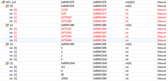
Stream SIO is created successfully. I let out 4 buffers by means of function SIO_issue. By a call of function SIO_reclaim the buffer does not come back.

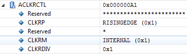
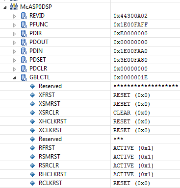
In a mode of debugging I looked through contents of all registers McAsp. I have noticed only one incorrect value. It is bit RCLKRST in register GBLCTL. It is cleared. It specifies that receive clock divider is held in reset.

I cannot understand in yet than the problem reason!!!

  • At cleaning of bit ASYNC in register ACLKXCTL on outputs McAsp there were signals. Function SIO_reclaim also does not return the buffer of the data.  There was a new problem. The processor does not react to change of contained field CLKRDIV of register ACLKRCTL. I installed its value 0x1.

    Frequency of a signal on output ACLKR remains equal 24 MHz. Though it should be equal 12 MHz. I again cannot define the problem reason. I will be very grateful to all answered.

  • I installed break point as Mcasp_localEdmaCallback. It not to time did not work. Thus function Mcasp_localEdmaCallback is never caused. Function SIO_issue is caused successfully.


    int ADC_buf[4][4];
    Ptr* rmt=NULL;
    for (int i=0; i<4;i++)
    {
    status_issue=SIO_issue(shandl, (Ptr)&ADC_buf[i][0], 4*sizeof(int), NULL);
    }
    
    
    However function SIO_reclaim is never returned.


    SIO_reclaim(shandl, rmt, NULL);


    In a debug mode I see that values of first two buffers are permanently updated.


    However queue contents fromdevice do not change. I ask experts of Texas Instruments to pay attention to my problem. Thanks.
  • korobchenko andrej,

    Let me go through the configuration and problem description, and get back to you.

    Thansks and Regards,

    Sandeep K 

  • korobchenko andrej,

    I have couple of suggestions and question for you,

    1. Have you tried with the mcasp sample application in the PSP? is it working?

    2. The sample application in the PSP makes use of instance '0' of mcasp. I guess you are also using the same instance.

    3. Can you please check the clock, is it the same as per the configuration? AUXXLK will be divided as per the value written in the 'HCLKRDIV' bit field of 'AHCLKRCTL' register. Refer the section 25.2.2 of OMAPL138 TRM .But as per your configuration the divider would be '1'. To divide clock from 'AHCLKR, to 'ACLKR', configure the bit field 'CLKRDIV' of register 'ACLKRCTL'.

    4. Is it possible get the snap shot of the McASP EDMA main PaRAM and other two Link PaRAMs after issueing all the buffers? 

    5. Can you try by enabling the hardware fifo (in the Mcasp_ChanParams)?

    6. What is the size of the buffer issued to the driver (i.e buffer size mentioned in the SIO_issue())?

    7. If possible can you try with single serializer/multiple slots by configuring the buffer format as 'Mcasp_BufferFormat_1SER_MULTISLOT_INTERLEAVED'. This is just for simplicity.

    Let us hope, with these information we can make application to work.

    Thanks and Regards,

    Sandeep K

  • Hello. Thanks that try to help me. Unfortunately, I could not answer your questions quickly. Has been very occupied. I tried audio an example and it worked. I allowed hardware fifo and the situation did not change. I tried buffers the different size and the situation did not change. Now the size of the buffer is equal 16000 byte. As you can see, it enough big buffer. I tried to use a format Mcasp_BufferFormat_1SER_MULTISLOT_INTERLEAVED and the situation did not change. Now frequency AUXCLK=24 MHz, HCLKRDIV=0 (Divide-by-1), CLKRDIV=1 (CLKRDIV). On an oscillograph I watch f (AHCLKR) = f (ACLKR) = 24 MHz. And should be f (ACLKR) = 12 MHz. 

    For date transmission the channel 0 EDMA is used. Value of register DST0 changes within address space of the two first transferred buffers. It also suggests that function Mcasp_localEdmaCallback is not caused. However the reason of it to me is not clear.

    I am sorry that could not answer in time. 

  • Hi,

    Are you using the OMAPL138 EVM or the custom board?

    Which instance of McASP, are you using?

    Can you please provide the McASP register dump just before strating the transfer and the EDMA register dump after starting the transfer?  

    Thanks and Regards,

    Sandeep K

  • For debugging of application I use a board omap-l138 experimenter kit firms Logic. 
    Also I apply other board which developed itself. Result identical. 
    By the way, I also in application apply driver SPI. It works perfectly.
    For the driver I use instance McASP0.

    Registers McASp to the date transmission beginning: 6404.McASP0.txt
    Registers EDMA after the date transmission beginning: 1464.EDMA.txt 
  • Hello! I cannot still localize an error. I will lay out the trimmed version of the project. In it all only is saved about communications with ADC. 3323.test_mcasp.zip

    Comments:

    1. The library ti.pspiom.mcasp_LPE.a674 is a library ti.pspiom.mcasp.a674 with usage -DMcasp_LOOPJOB_ENABLED

    2. The library ti.pspiom.gpio_8_15.a674 is the changed library ti.pspiom.gpio.a674. In it I rectified an error which is not allowing me to use GPIO 8 [15].

    I hope for your help.

  • Apologies for the delayed response, I was on vacation.

    Let me check the register dump and the project shared by you.

    Thanks and Regards,

    Sandeep K

  • Hi,

    I have gone through the aco_mod.tcf file, please refer the "\pspdrivers_01_30_01\packages\ti\pspiom\examples\evm6748\mcasp\build\mcaspSample.tci" and modify your .tcf file, since there are some fields missing in your tcf file (like no deviceid for mcasp etc). To begin with you can just copy & paste the PSP tci file content to your tcf file.

    Let me know the result.

    Thanks and Regards,

    Sandeep K

  • Hello. I have corrected tcf a file. I have added next lines:

    bios. UDEV.instance ("mcasp0").deviceId = 0;

    bios. DIO.instance ("Mcasp_in").deviceName = prog.get ("mcasp0");

    bios. DIO.instance ("Mcasp_in").useCallBackFxn = false;

    Me has surprised that these lines were not generated automatically. I entered these parametres in a graphic mode. Henceforth I will be more attentive. Unfortunately, today I can not give the information on results of debugging of the program. Today, because of bad weather (-40 degrees on Celsius) it was necessary to work at home. Tomorrow I will reach laboratory. Then I will write about results of debugging on a debugging payment. 

  • I checked up the project with the updated file tcf. Unfortunately, the same result.

  • korobchenko andrej,

    How is weather now?

    I have gone through the project shared by you and accordingly I have written an example (tcf) file, please find the attached file. I assume you are using the mcasp instance '0'.

    Delete all the entries releted to mcasp in the tcf file and add the entries in the attached file.

    With this, you sould be getting the clock as per the divider value. Once the clock is appropriate then we can proceed further. The clock ACLKR should be equal to the bit rate in which the data is coming into the mcasp receive pin.

    Eg: For 32 bit slot size, 2 slots and 48KHz sample frequency, the ACLKR should be (32 * 2 * 48K) ~ 3.072MHz

    Let me know the result.

    Thanks and Regards,

    Sandeep K

  • Hello. Weather excellent. The Siberian siesta ended. I edited tcf a file. As a result the situation, unfortunately, did not change.
    At calculation of frequency of clocking I address to this picture. (I notify, I made less frequency ACLKR, than in the project published by me.)

    Now at me the following situation with clocking. AUXCLK=24 MHz.. Coefficient HCLKRDIV=1. Coefficient CLKRDIV=6.

    If to follow a manual should be such situation : AHCLKR=24 MHz, ACLKR= 4MHz ,  AFSR=ACLKR/64=62.5 kHz.

    But I watch the following: AHCLKR=ACLKR= 24MHz ,  AFSR=ACLKR/64=375 kHz.

    The system does not react to change of coefficient CLKRDIV in any way.

    The system reacts only to change of coefficient HCLKRDIV. For example, at HCLKRDIV=6: AHCLKR=ACLKR= 4MHz ,  AFSR=ACLKR/64=62.5 kHz.

  • It is nice to hear that the weather is back to normal :)

    With respect to mcasp clock, i want you to check two things,

    1. "PFUNC" register values. As per the shared code, function mcaspUserInit() make all the pins (except the reserved bit) to 1, i.e to act as a gpio pin. Instead it should have been configured to act as a mcasp pin (refer the PFUNC register description in the mcasp manual)

    2. The bit fields "RCLKRST",  "RHCLKRST", "RSRCLR, "RSMRST" and "RFRST" in the "GBLCTL" register should be made one, this will make all of then to be active. But as per the snap shot in the previous conversation, it looks like the bit "RCLKRST" is '0', which explains why the CLKRDIV is not getting reflected. Step through the function Mcasp_localConfigRcvSection() in the mcasp. file to find out why it is not being set.

    One more important thing is, while allocating the valid buffer or the loopjob buffer, you need to make sure that the length of the buffer should be multiple of - slot size in number of bytes * number of slots * number of serializers.

    Hope this would help you to resolve the issue.

    Thanks and Regards,

    Sandeep K

  • With register PFUNC everything is all right. Possibly configuration of clothespins is produced by the driver code. Here contents of this register:

    I analyzed the code of function Mcasp_localConfigRcvSection (). I found an error admitted by the developer of the driver. 

    At first it was necessary to initialize register ACLKRCTL. Only then check up a state of bit CLKRM. I changed places of these two units of the code. As a result signals of clocking of a steel adequate the correct.  However, unfortunately, it did not solve a shared problem.

    At present AUXCLK=24 MHz, AHCLKR=24 MHz, ACLKR=4 MHz, AFSR = 62.5 kHz.

  • korobchenko andrej,

    The reset value for CLKRM is aways '1' and which indicates as internal clock generation. So, the code will work unless we modify the ACLKRCTL register somewhere else in the driver.

    Anyway, now you are getting the clock as per the configuration.

    Coming to the actual issue, at what point the mcasp is stuck? Is it coming out of SIO_issue()? If it is coming out of SIO_issue(), but not coming to the edmacallback, then pause the execution and get the snap shot of the EDMA PaRAM to know the status of the transaction.

    I guess, you are using the loopjob buffer. If yes, then please verify the loopjob buffer length as per the the buffer format being used. 

    Thanks and Regards,

    Sandeep K


  • Call SIO_issue is completed successfully (status_issue it is always equal 0). I use loopjob buffer. Its size is equal 16000 byte. It is multiple to value   2 (number of slots) X 2 (number serializs) X 4 (word length).  To avoid a situation snap shot of the EDMA PaRAM I reduced frequency AFSR (62.5 kHz) and increased the size of the buffers, participating in an exchange (16000 byte). 

  • You can get the EDMA Link PaRAM address in pramTblAddr[] and the main PaRAM address is 0x01C04000 (since McASP RX EDMA event number is '0').

    If you look at these PaRAM values, the state of the EDMA transfer would be found. If you share this, i can try to analyse it.

    Regards,

    Sandeep K


  • pramTblAddr[0]=0x1C04400 (Parameters Set 32),  pramTblAddr[1]=0x1C04420 (Parameters Set 33). Contents of Registers Parameters Set 0 during transmission. 1884.ParamSet_0.txt

    Contents of registers ParamSet 32 and 33 during transmission:

    In the channel are transferred buffers ADC_buf [4].  The address of buffer ADC_buf [0] - C0030000 (he can be seen in register DST Parametr_Set32), ADC_buf [1] - C0033E80 (he can be seen in register DST Parametr_Set33), ADC_buf [2] - C0037D00, ADC_buf [3] - C003BB80. Program performance is locked on the first SIO_reclaim. Thus contents of buffers ADC_buf [0] and ADC_buf [1] regularly change. Alternately PaRAM_0 linking with PaRAM_32 and PaRAM_33. Thus contents of registers ParamSet_32 and ParamSet_33 (including registers SRC) NEVER CHANGE.

  • Sincere apologied for the delay. :(

    If the Main PaRAM is shifting between PaRAM_32 and PaRAM33, then there is an EDMA transaction happenning. Have you tried to put breakpoint in the EDMACallback function?

    Always the EDMA main PaRAMs will be consumed by the EDMA and not the link PaRAMs(PaRAM_32 and PaRAM_33). So the Link PaRAMs value will never change. It will be copied to the main PaRAM and then consumed by the EDMA.

    Are you able to probe the data at the McASP output pin?

    Thanks and Regards,

    Sandeep k 

  • Hello! I clearly see on the oscillogram signals of the data on inputs AXR8 and AXR10. I delivered breakpoint in function Mcasp_localEdmaCallback. The program never reaches it.

  • Hi,

    The below observations indicates that there should be an invocation of EDMA callback function in the mcasp_edma.c file,

    1. If you look at the PaRAM 0, it is toggling between link PaRAMs (PaRAM 32 and 33).

    2. The EDMA PaRAMs are configured to generate the EDMA completion interrupt.

    3. The IPR register of the EDMA is 0x00000001, i.e bit '0' is set which means an interrupt for the event '0' (which is nothing but the mcasp rx event number).

    4. All the mcasp clocks are as per the configuration.

    5. Cannot doubt the Pinmuxing, since all the signals are seen on the oscilloscope. 


    Is this the only application running on the DSP? Do you have anything running on the ARM?

    Can you please share the mcasp and the EDMA register dump after calling the SIO_reclaim()? 

    Thanks and Regards,

    Sandeep K


  • On ARM the image Linux which by default is in SPI storages boots. For ARM and DSP I debug programs separately. For ARM on the basis of Linux I have already finished the program. It is necessary to implement DSPLINK. Also it is necessary to solve problem MCASP. Here contents of registers MCASP and EDMA after call SIO_reclaim.  

    6406.Dump_MCASP.txt

    8473.Dump_EDMA.txt