


Other Parts Discussed in Thread: TMS320F28335
Tool/software:
Hi TI experts,
We are currently debugging SPI communication issues between an ARM (AM335x) and a DSP (TMS320F28335). We noticed that although both platforms have the same physical SPI mode (for example, both are set to CPOL=1, CPHA=0), the numeric definitions and the resulting timing diagrams appear to be different between the ARM and the DSP documentation.
1. Reference Material
• On the ARM side (AM335x), SPI Mode 2 is defined as CPOL=1, CPHA=0.
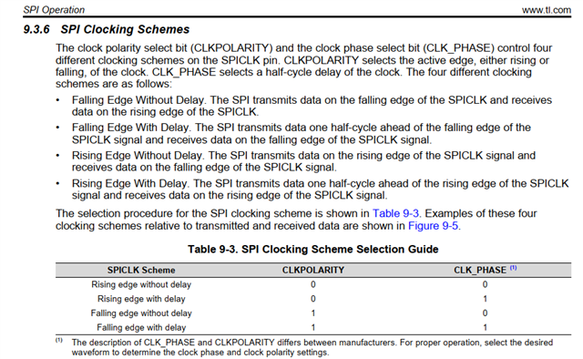
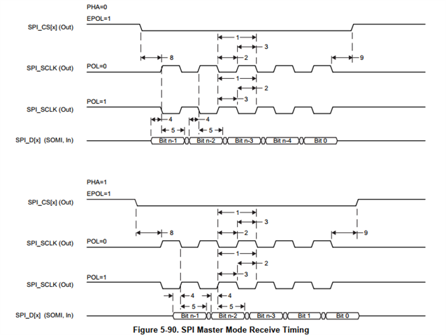
• On the DSP side (TMS320F28335), the SPI register bits and timing diagrams seem to interpret CPOL/CPHA slightly differently.
(See attached screenshots below for documentation examples.)
2. Our Confusion
Even when we set both devices to the “same” SPI mode (e.g., CPOL=1, CPHA=0), we sometimes observe data misalignment or timing issues. The timing diagrams in the manuals for ARM and DSP for the same CPOL/CPHA settings also look different in terms of clock/data relationship.
- Why are the numeric definitions of CPOL/CPHA not fully consistent across different TI chips?
- How should we reliably match the SPI modes between AM335x and TMS320F28335?
- Is there an official TI recommendation for cross-platform SPI configuration to avoid such confusion?
3. Screenshots/Reference
4. Additional Info
• Both sides run at 1.5 MHz SPI, master is ARM, slave is DSP.
• Data format: 8 bits.
• We observe data misalignment or communication interruption especially after power-on.
Any advice or clarification would be highly appreciated!
Thanks,
[Chenlon/Kangni]
