Other Parts Discussed in Thread: UNIFLASH, LP-AM243
Tool/software:
Problem description:
After the AM6442 chip on the self-designed PCB enters DFU boot mode, when using USB 2.0 to program SBL and APP, the host shows: "Unknown USB device (Device descriptor request failed)".
Relevant debugging results:
1.Compared the operation and results of USB DFU on the AM6442-EVM evaluation board. Under the condition of ensuring the operations are correct, the differential signals of the USB D and D- connections were measured separately using an oscilloscope. The summary is as follows:
1)On the self-designed PCB the signal data for RBL drives USB in DFU boot mode is shown in the table below:
|
Time(us) |
100000 |
150 |
1100 |
25 |
50 |
50 |
50 |
50 |
50 |
2.5 |
50 |
50 |
… |
50 |
50 |
50 |
|
Voltage(v) |
3 |
0 |
-0.5 |
0 |
-0.8 |
0.8 |
-0.8 |
0.8 |
-0.8 |
0.8 |
0.5 |
-0.5 |
… |
0.5 |
-0.5 |
0.5 |
Note:There are a total of 1067 50us levels of data marked in red, alternating between high and low levels, with the last level being a high level.
2)After the SD card boot starts, the USB signal is driven, and the signal content is as follows in 4 parts:
The first part of the signal is as follows.
|
Time(us) |
100000 |
150 |
1100 |
25 |
50 |
50 |
50 |
50 |
50 |
2.5 |
50 |
50 |
… |
50 |
50 |
50 |
|
Voltage(v) |
3 |
0 |
-0.5 |
0 |
-0.8 |
0.8 |
-0.8 |
0.8 |
-0.8 |
0.8 |
0.5 |
-0.5 |
… |
0.5 |
-0.5 |
0.5 |
Note:There are a total of 1067 50us levels of data marked in red, alternating between high and low levels, with the last level being a high level.
The remaining 3 parts of the signal content are as follows:
|
Time(us) |
500000 |
25 |
50 |
50 |
50 |
50 |
50 |
2.5 |
50 |
50 |
… |
50 |
50 |
50 |
|
Voltage(v) |
0 |
0 |
-0.8 |
0.8 |
-0.8 |
0.8 |
-0.8 |
0.8 |
0.5 |
-0.5 |
… |
0.5 |
-0.5 |
0.5 |
|
Time(us) |
500000 |
25 |
50 |
50 |
50 |
50 |
50 |
2.5 |
50 |
50 |
… |
50 |
50 |
50 |
|
Voltage(v) |
0 |
0 |
-0.8 |
0.8 |
-0.8 |
0.8 |
-0.8 |
0.8 |
0.5 |
-0.5 |
… |
0.5 |
-0.5 |
0.5 |
|
Time(us) |
500000 |
25 |
50 |
50 |
50 |
50 |
50 |
2.5 |
50 |
50 |
… |
50 |
50 |
50 |
always |
|
Voltage(v) |
0 |
0 |
-0.8 |
0.8 |
-0.8 |
0.8 |
-0.8 |
0.8 |
0.5 |
-0.5 |
… |
0.5 |
-0.5 |
0.5 |
3 |
Note:The part marked in red after each segment of the signal has 1067 levels of 50 microseconds, these levels alternate between high and low, ending with a high level.And the last signal part is a continuous high level of 3V.
3)There is a significant difference in the signals on the AM6442-EVM evaluation board when successfully running the USB DFU function. Whether during the RBL phase driving the USB device as an AM64x DFU device or after the SBL driving the USB as an AM64x-AM243x DFUS device, the signals captured by the oscilloscope are the same, as shown below:
|
Time(us) |
100000 |
150 |
1200 |
25 |
50 |
50 |
50 |
50 |
50 |
2.5 |
50 |
50 |
… |
50 |
50 |
|
Voltage(v) |
3 |
0 |
-0.5 |
0 |
-0.8 |
0.8 |
-0.8 |
0.8 |
-0.8 |
0.8 |
0.5 |
-0.5 |
… |
0.5 |
-0.5 |
Note:In the red-highlighted part of the data, there are a total of 222 50us levels, alternating high and low levels, with the last level being low.
2.After the RBL is initiated, the host burns the "sbl_dfu_uniflash.Debug.hs_fs.tiimage" image into the AM64x DFU device to change the clock frequency-related parameters uint32_t clkSrcSel and uint32_t pllRefSel in the USB driver source code static usb_init_param_t gUsbInitParam. However, whether on the AM6442-EVM evaluation board or on a custom-designed PCB, the actual clock frequency cannot be changed. The value of the CFG0_USB0_PHY_CTRL register has consistently been observed as 0x80000004 (the recommended(maybe default) value in the TRM manual) on both boards through JTAG.
Additional information:
Chip information on self-designed PCB:SITARA AM6442B SEGHAALV 35PLDLS 709 GL
Chip information on AM6442-EVM: SITARA AM6442B SEGHAALV 28PL6KS 709 GL
Serial number: 4963;
Host device information: Operating system 64-bit Windows 10 Professional Workstation version laptop
Communication bus: USB2.0;
Physical interface: TinyUSB.
MCU+SDK version:11.00.00.15(mcu_plus_sdk_am64x_11_00_00_15)
Overall diagram of the USB signal on the self-designed PCB board in SD card bootmode:
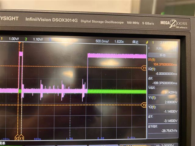
Detailed diagram of the USB signal on self-designed PCB board in SD card bootmode:

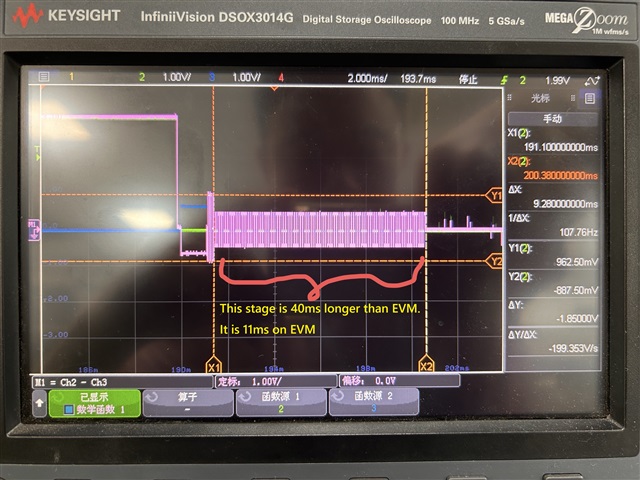
Overall diagram of the USB signal on the self-designed PCB board in DFU bootmode:
Detailed diagram of the USB signal on the self-designed PCB board in DFU bootmode:

Detailed diagram of the USB signal on the AM6442-EVM board in DFU bootmode:

Questions:
1) What does the difference in the USB handshake messages on the two boards mean as described in the problem? What should we do to fix the USB?
2) Does the AM6442 chip itself support USB 2.0 high-speed mode? Does an external PHY chip need to be used to support high-speed mode?
Additional HW information 20250924:
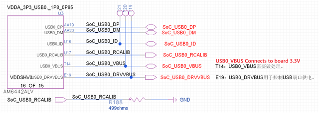
The hardware design diagrams related to USB are shown in the three images below:
1)USB pin connection on SOC side, VBUS connects to board 3.3V, also tried with 5V with resistor divider, same result.
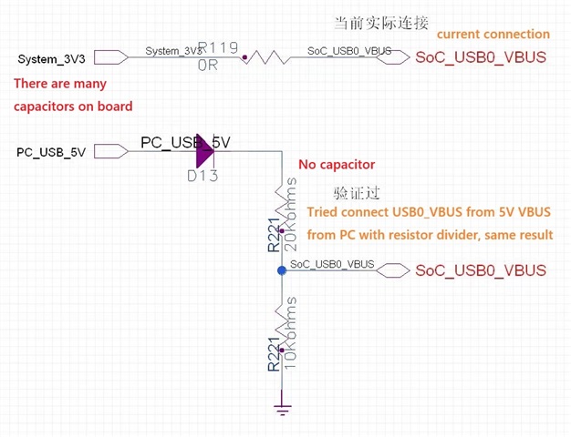
2)USB board connection, component in BLUE frame is unmounted for test. R144 and R145 are 0ohm
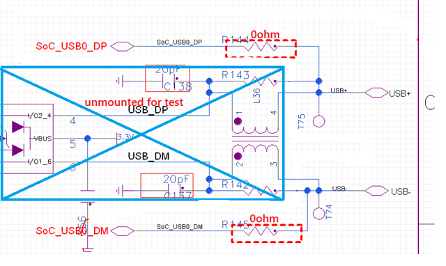
3)Type-C connector, USB differential equal length, differential impedance DIFF-90R
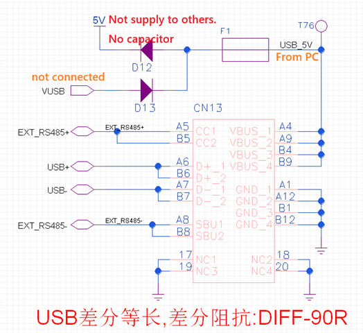
In addition to the foundation shown in the above three pictures, there are also the following attempts at changes and debugging:The ID is floated, and the vbus pin is changed to a voltage divider with 20k/10k resistors to 5V.