Part Number: AM625
I want to integrate sdl_rti_example_uc2_am62x-sk_m4fss0-0_nortos_ti-arm-clang into our project.
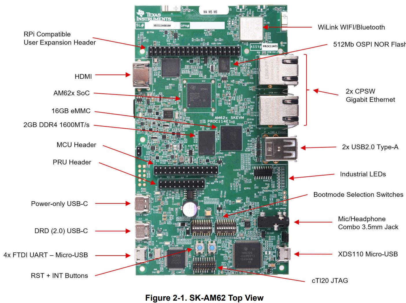
Firstly, the example runs well on the below EVM board. here are my steps on EVM.
1. replace M4F image with sdl_rti_example_uc2 demo image in config file, /opt/1Twork/repository/mcu_plus_sdk_am62x_10_01_00_33/tools/boot/sbl_prebuilt/am62x-sk/default_sbl_ospi_linux_hs_fs.cfg..
from
--file=../../examples/drivers/ipc/ipc_rpmsg_echo_linux/am62x-sk/m4fss0-0_freertos/ti-arm-clang/ipc_rpmsg_echo_linux.release.appimage.hs_fs --operation=flash --flash-offset=0x100000
to
--file=../../examples/sdl/rti/UC2/am62x-sk/m4fss0-0_nortos/ti-arm-clang/sdl_rti_example_uc2.release.appimage.hs_fs --operation=flash --flash-offset=0x100000
2. using the config to write images to flash.
3. power on EVM.
Our project uses a different boot flow with the default EVM board(Use the SBL).
Below is our project boot flow, SPL boot flow in LINUX SDK.
When use the uboot to boot the same sdl_rti_example_uc2_am62x-sk_m4fss0-0_nortos_ti-arm-clang.out. From the uart log, we see that ESM interrupt cannot get into.
Due to it is a watchdog example, when it cannot get into the ESM interrupt, it resets the SOC chip

[11:18:52.286]
RTI Example Test Application
RTI_Test_init: Init MCU WKUP complete
RTI Example code UC-2 started
DWWD configured to 50 percent window size
DWWD is configured for 10000 ms time-out
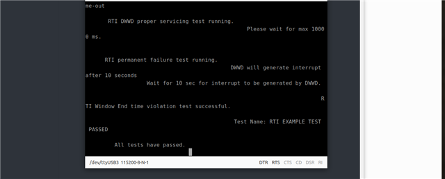
RTI DWWD proper servicing test running.
Please wait for max 10000 ms.
RTI permanent failure test running.
DWWD will generate interrupt after 10 seconds
Wait for 10 sec for interrupt to be generated by DWWD.
[11:19:10.186]
RTI Example Test Application
RTI_Test_init: Init MCU WKUP complete
RTI Example code UC-2 started
DWWD configured to 50 percent window size
DWWD is configured for 10000 ms time-out
RTI DWWD proper servicing test running.
Please wait for max 10000 ms.
RTI permanent failure test running.
DWWD will generate interrupt after 10 seconds
Wait for 10 sec for interrupt to be generated by DWWD.
[11:19:28.084]
RTI Example Test Application
RTI_Test_init: Init MCU WKUP complete
RTI Example code UC-2 started
DWWD configured to 50 percent window size
DWWD is configured for 10000 ms time-out
RTI DWWD proper servicing test running.
Please wait for max 10000 ms.
RTI permanent failure test running.
DWWD will generate interrupt after 10 seconds
Wait for 10 sec for interrupt to be generated by DWWD.
[11:19:45.985]
RTI Example Test Application
RTI_Test_init: Init MCU WKUP complete
RTI Example code UC-2 started
DWWD configured to 50 percent window size
DWWD is configured for 10000 ms time-out
RTI DWWD proper servicing test running.
Please wait for max 10000 ms.
RTI permanent failure test running.
DWWD will generate interrupt after 10 seconds
Wait for 10 sec for interrupt to be generated by DWWD.
[11:20:03.892]
RTI Example Test Application
RTI_Test_init: Init MCU WKUP complete
RTI Example code UC-2 started
DWWD configured to 50 percent window size
DWWD is configured for 10000 ms time-out
RTI DWWD proper servicing test running.
Please wait for max 10000 ms.
RTI permanent failure test running.
DWWD will generate interrupt after 10 seconds
Wait for 10 sec for interrupt to be generated by DWWD.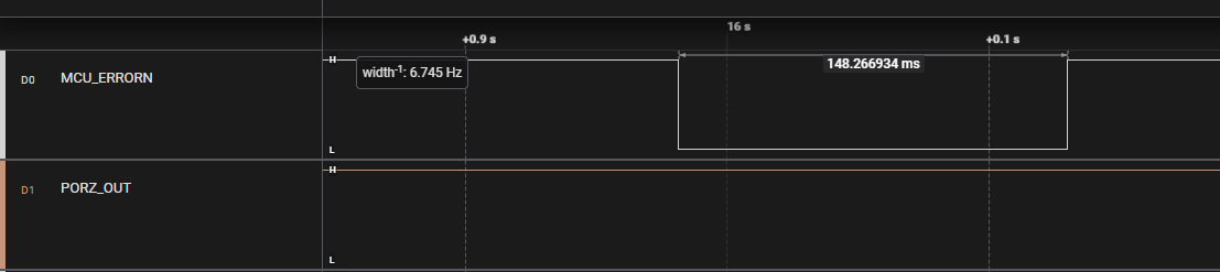
When RTI watchdog timeout, the MCU_ERRORN toggled from high to low.
Question:
Are there sequences that need to be taken care? Such as when entering into the M4F main function, try to give a clean ESM environment.
But I do not find the SDL_ESM_deinit function, or clear all interrupt flags.