Part Number: AM62P
Other Parts Discussed in Thread: SYSCONFIG


This thread has been locked.
If you have a related question, please click the "Ask a related question" button in the top right corner. The newly created question will be automatically linked to this question.
Part Number: AM62P
Other Parts Discussed in Thread: SYSCONFIG


Hello Fan,
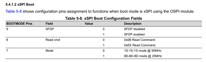
When using xSPI but without SFDP enabled, the ROM expects the 4 byte address to be sent as per the bootmode description. You can read this under the xSPI bootloader description from the TRM.
Now the flash, when it undergoes a PORz and ROM starts booting, is in a reset state which means it is in 3 bytes addressing state.
This also means that the NVCR is actually configured by default to 3 byte addressing, and hence this value gets copied to VCR itself.
So in order to boot purely in 8D-8D-8D, I see that you would need to set NVCR to 4 byte addressing such that upon PORz, the reset value is 4 byte addressing itself, and hence the booting will take place.
One the frequency question which you have:
Can you please recheck if the frequency is actually 5 MHz or you measured it incorrectly. Please confirm on this front.
Looking forward to your response.
Kind Regards,
Vaibhav
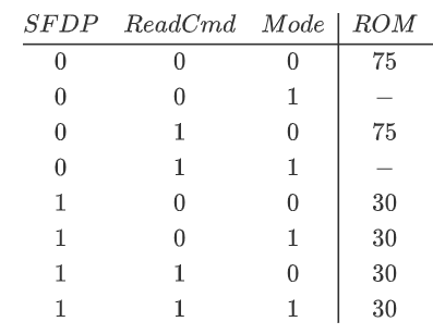
I think the boot process will not be affected whatever bootmode pin 7 and 8 are configured when bootmode pin 9 is set 1
Yes your understanding is correct, it will be a NO CARE, when SFDP is enabled, but it is always a good practise to have them at 0, reason being we have not validated for numerous boot cycles if having 7, 8 as any random value when SFDP is enabled does not cause any issue. So in theory yes 7, 8 will be a NO CARE, but good to set it to 0.
Hi Vaibhav,
Can you please recheck if the frequency is actually 5 MHz or you measured it incorrectly. Please confirm on this front.
I have double-checked the measurement of 5MHz and I think my measurement is correct. I could attach the relevant screenshots below.

Regards,
Bomiao
Hi Fan,
Thanks for mentioning this. I am reviewing this and will get back to you in sometime.
Regards,
Vaibhav
Hi Bomiao,
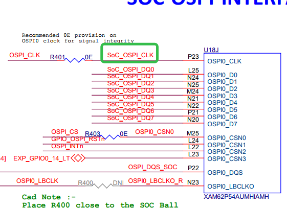
You should be measuring the R415, and not R410 to see the proper clock.

Regards,
Vaibhav
Hi Vaibhav,
For measuring the signal of OSPI_CLK, I think R415 and R401 are equivalent. Now I could get 50MHz when measuring the OSPI_CLK during ROM and SBL 1 after adjusting the parameter of oscilloscope. Sorry about my mistakes.
I have further questions about configuring the OSPI_CLK in Sysconfig. In example project "sbl_ospi_linux_stage1_am62px-sk_wkup-r5fss0-0_nortos_ti-arm-clang", the OSPI driver is enalbed with its clock set as 166666666Hz and input clock divider set as 4. The related screenshot is attached below. Does this means the OSPI_CLK is 41.6MHz during SBL1? If so, I think there is a contradiction because the OSPI_CLK I measuring during SBL1 is 50MHz.

Additionally, I wonder the relationship between the OSPI_CLK configured by Sysconfig in SBL1 and the clock tree of OSPI. I want to ask which specific part of OSPI clock tree corresponds to the input clock frequency 166MHz along with clock divider mentioned in Sysconfig. I attached the screenshot of OSPI clock tree below.

Regards,
Bomiao
Hello,
Glad to see you get 50 MHz on the oscilloscope after setting the correct configurations.
For the SBL, in stage 1 and stage 2, we just do reading.
Please refer this OSPI PHY Tuning FAQ, in general to gain awareness on what is PHY Tuning and how it improves the FLASH Read Speed.
FAQ: [FAQ] AM62x, AM62Ax, AM62Px, AM62D-Q1, AM64x, AM243x: OSPI Phy Tuning Algorithm
This will answer your query.
Kind Regards,
Vaibhav
Please read this after you have referred the FAQ:
You will see that the 166 MHz is the speed, and the clock divider is bypassed, in this case 4 is bypassed as PHY is checked.
Hope this helps.