I have a new board with an HMC6343. I've tested two boards and they both give the same result. I have an otherwise working DM6467 system with lots of working I2C. But it won't work with the HMC6343. I realize this sounds a lot like a "HMC6343" question and not a "DM6467" question. But I've already tried with the manufacturer with no success. I end up asking a specific DM6467 question in question #2 further below.
I've temporarily modified my code to run a dedicated loop accessing ONLY the HMC6343. I have reduced things to simply sending an address byte 0x32 followed by a command byte, the paitr occurring every 250ms. However, I fail to get an ack at the end of the address, which makes it seem that the HMC6343 is not responding to the address. (And thus the command byte isn't sent at all.) I've contacted the manufacturer and I know the address is correct, comparing his scope traces to mine. We haven't been able to figure it out yet.
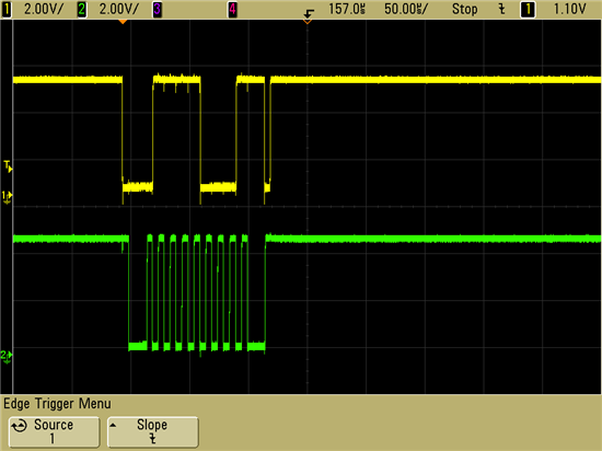
The attached below "HMC6343 scope trace.JPG" shows what I see on the oscilloscope. The address 0x32 is sent (including lsb lor for write), but at the 9th rising edge, the data line is back high. I believe this means the HMD6343 is NOT acknowledging the address. A moment later, the master realizes this and gives up with a stop bit. This repeats every 250ms. On the attached jpg, there are two vertical dotted cursors. It's about clock rise marked by the rightmost cursor that I should be seeing the data
So I can't figure out why the HMC6343 is not acknowledging the address.
My clock rate is about 81kbps. This is below the 100kbps spec. It's the default that legacy TI code on their DaVinci chip uses. I certainly hope that running slower than 100kbps is not a problem for the HMC6343.
So TWO QUESTIONS:
1) Do you have any OTHER ideas why the chip is not giving me an ack in recognition of the address, and
2) How can I change that 81kbps that I inherited from the EVM and DVSDK, either up to 100kbps in case the chip crazily requires fully this speed, or down to something slower in case it doesn't like my data-to-clock setup times?
Thanks very much,
Helmut
"HMC6343 scope trace.JPG" from my system below. See right cursor at 9th rising edge of clock. Chip not pulling data low as it should
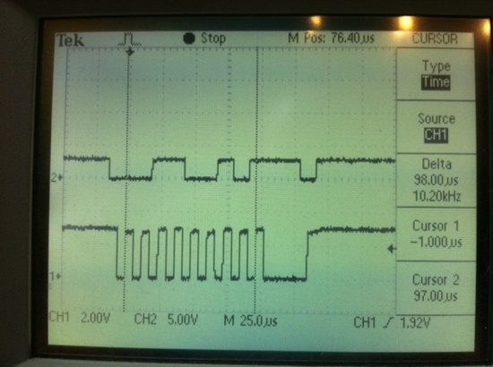
"HMC6343 0x32_0x50.png" from manufacturer. His data and clock are identical to mine, except he DOES get the nack from the chip. in fact, you can see the data pull a little lower on the data line for the nack time period (twice, one nack for the address, and one nack for the followup data byte that he IS able to send).
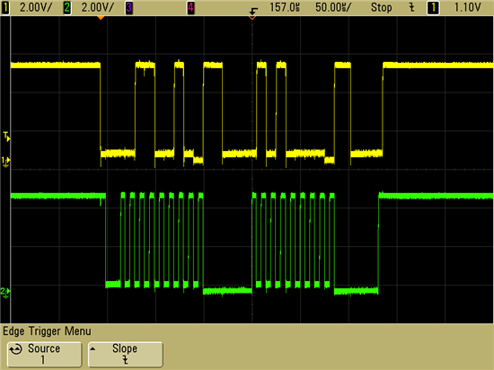
"HMC6343 0x78 0x50.png" Another graph from the manufacturer, showing a nack response that he forced by providing the wrong address. Aside from the address bit values, this one looks more like mine. So indeed my trace looks like the chip isn't recognizing the address I'm giving.