Part Number: LP-AM263
Other Parts Discussed in Thread: UNIFLASH
Hi,
My team has been trying to debug project on LP-AM263 but we have not been able to do so. We have tried two sample projects for the same. This are provided by TI & we have not changed a single code line. Projects are rpmsg_echo_callback & empty.
We have tried two methods to debug projects
- CCS Launch, Load and Run Link
- A brief of what we do, set mode = 1 to enable dual core configuration in gel file
- SOC Init with SBL_Null flash (As per TI's guide Link). This includes Flashing SBL_NULL bootloader in UART Mode & Power Cycle in QSPI boot & verify NULL BootLoader is flashed.
- Launch a project-less debug in CCS.
- We connect to R5_0 which does gel config for R5_0 core
- Reset core & load binary
- Repeat for core R5_1, R5_2 & R5_3.
- Create a core group.
- Run all cores simulaneously using core groups.
- One Click Debug Mode Link
- This is a simply straightforward method.
- Import Project in CCS
- Build Project
- Start Debugging by clicking Run->Debug Project
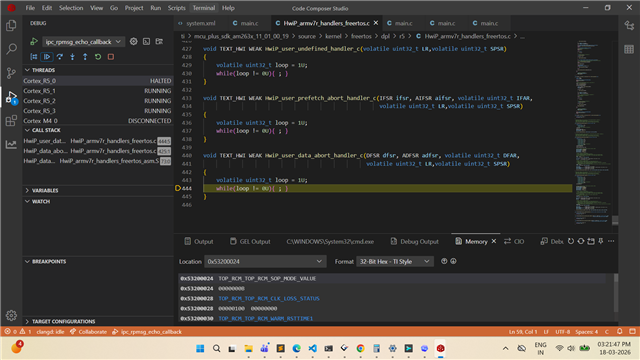
In both the methods, debugging doesn't work. We have an error on R5_0 core attached as per attached Screenshot. Code loops under HwiP_user_data_abort_handler_c.

NOTE: Project works when it is flashed using Uniflash Tool or uart_uniflash.py. Which indicate that problem is with debugging the code and not the application logic.
TI Uniflash Tool: sbl_ospi_multicore_elf.release.tiimage & Multicore Application Image (Flashing in UART Boot, Flash, Power Cycle & QSPI boot)
Uart Uniflash Py: sbl_uart.release.tiimage & Multicore Application in UART Boot Mode (Flashing in UART Boot)