This thread has been locked.

If you have a related question, please click the "Ask a related question" button in the top right corner. The newly created question will be automatically linked to this question.

AM6442: AM6442 Internal PCIe REFCLOCK Fail in Compliance Test

Part Number: AM6442

Hi Team ,

Building on our previous discussion documented at
https://e2e.ti.com/support/processors-group/processors/f/processors-forum/1620903/am6442-resistor-selection-for-am6442-internal-pcie-refclock

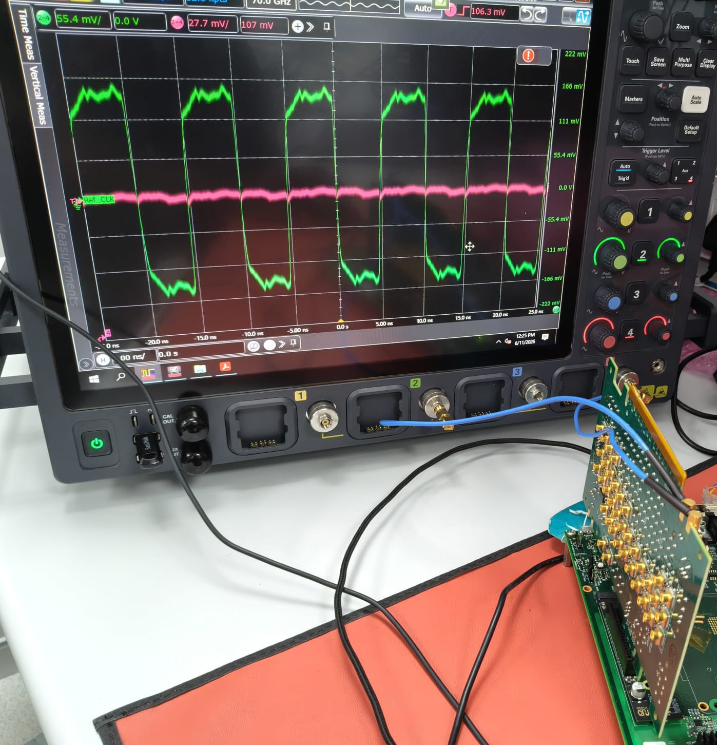
we have recaptured the AM6442 internal PCIe reference clock using a PCIe load board as part of our updated test setup. Following this modification, the measured jitter performance now meets the compliance requirements. We used SMP to SMA cable to to capture the clock signal.

However, we are observing marginal failures in the following signal integrity parameters during compliance validation:

  • Rising edge rate
  • Absolute crossing point voltage

We have attached the latest compliance test report along with detailed images of the measurement setup for your review.

We request your guidance on:

  1. Potential root causes for these marginal deviations
  2. Recommended next steps to mitigate these issues and achieve full compliance

load board.pngPCIe_CLK_Report_2026-06-15_11-36-12_two_fail.pdf IMG-20260615-WA0004.jpg

  • Greetings Aditya,

    I am glad to see the signal looks better when using a compliance board compared to before. My initial thoughts on what you're seeing revolve around the termination of the clock signal. Few initial questions:

    1. Does the board this report was captured on have any external termination resistors present? 
    2. This may be a question for the scope manufacturer on your end, but is the input of the scope terminated at 50 ohms or some other value?

    Sincerely,

    Lucas

  • Hi Lucas,

    Thank you for the quick response. Please find my answers to your questions below.

    1. Does the board this report was captured on have any externa termination resistors present?

    Ans: No


    1. This may be a question for the scope manufacturer on your end , but is the input of the scope terminated at 50 ohms or some other value?

    Ans: We are using the SMA to SMP cables with standard termination of 50 ohms at the probing end.

  • Greetings Aditya,

    What about the scope inputs themselves? The scopes I've seen for this type of work usually have their input impedance set to 50 ohms, but some scopes can have a configurable input impedance depending on their complexity. 

    Sincerely,

    Lucas

  • Hi Lucas , 

    We had discussion with Keysight team reagrding the scope channel termination. And they confirmed that channel haa a termination of 50 ohms. Attached reply snipshot from Keysight Team.  And let us know how to disable internal terminations in AM6442 for the REFCLK. Kindly let us know how to proceed further.   


  • Greetings Aditya,

    That's good to confirm with the scope vendor.

    Under normal circumstances, disabling the internal termination properly has to be done as a specific part of the SERDES initialization. It's possible to do so after initialization as a debug step for the behavior you're seeing, but just to be clear: this method of disabling the internal termination is not meant to done in real operation. Because it's not being done as part of the proper sequence, it's also possible there are other unknown electrical or functional effects to the interface from this debug step, but it should be effective in removing the double termination of the clock signal for your measurement.

    It's important that the REFCLK output has at least one 50ohm termination path to ground at some point in the path not only for proper signaling, but also to avoid causing potential damage to the part. In this specific case the scope you are using is providing that, but on the actual board it's unlikely the endpoint device will provide this path. We cannot debug or provide support for a part that has been potentially damaged by disabling the internal termination with a board that has no termination. Be careful with testing the below register sequence and ensure whatever platform is being tested is properly set up.

    You should be able to disable the termination like so on AM64x specifically for this debug:

    • Clear bit 31 of 0x0F00040C
    • Set bit 27 of 0x0F00040C
    • Set bit 31 of 0x0F00040C
    • Clear bit 5 of 0x0F0000A0

    Again, all caveats/warnings above apply.

    Sincerely,

    Lucas

  • Hi Lucas,

    Thank you for the detailed inputs and the clarifications regarding the debug approach and associated risks.

    Based on your comments, I would like to seek a few clarifications to ensure correct implementation on our side:

    1. Register Scope Clarification
      Could you please confirm whether the registers mentioned below:

      • 0x0F00040C
      • 0x0F0000A0

      belong to the AM64x SERDES wrapper/register space, or are these part of the Cadence PHY (CSL/PHY internal) registers?

    2. Register Documentation
      Could you point us to the appropriate TRM section or documentation where these registers and their bit fields are described?
      (We were unable to locate these explicitly in the publicly available AM64x TRM.)

    3. Software Integration Point (SDK 10.00.07.04)
      We are currently using Processor SDK 10.00.07.04. Could you suggest:

      • The recommended software layer to apply these register writes (e.g., SERDES init sequence, board init, or a low-level driver such as CSL/PHY driver)?
      • Any specific file/module where such debug overrides are typically added?
    4. Initialization Sequence Dependency
      Since you mentioned that proper termination handling should ideally be part of the SERDES initialization sequence, is there any reference flow or example where this configuration is handled correctly during initialization (instead of post-init debug override)?

    We will ensure that proper termination is always present on the platform during testing and will use this only for controlled debug purposes.

    Looking forward to your guidance.

    Regards,
    Shwetha Nayak

  • Greetings Shwetha,

    I do not believe we describe these registers, outside of debugging they are not typically meant to be adjusted by customers.

    You can perform the register write sequence after the SerDes and PCIe configuration, the software layer would be like an application in user-space (I'm not super familiar with the Linux SDK so this may be phrased wrong). In the MCU+SDK this would be equivalent to running after "Board_driversOpen" has been called. There is no reference flow for this as far as I know. Please give it a try to see if it improves the behavior you're seeing.

    Sincerely,

    Lucas

  • Hello Lucas,

    Thank you for your response. We are currently working on the A53 core of the AM64x, with a primary focus on Linux. Could you please connect us with the appropriate Linux expert for further assistance?

    Regards,

    Shwetha