This thread has been locked.

If you have a related question, please click the "Ask a related question" button in the top right corner. The newly created question will be automatically linked to this question.

timer_test code in an application that is also using NDK

hello,

I am trying to track down why and how these two applications are related.  When I don't include the timer example, then my ndk runs fine.  When I run the test function, the ndk will stop working and responding to network messages.

Versions: C6678, bios_6_32_05_54, ndk_2_200_05_17, pdk_C6678_1_0_0_17

Please help me to understand how these two are related.

Also, when I run the function, the value of timerISRCounter is always 2, another mystery. 

Thanks!

Brandy

Here is the call from CORE_0

test_gp_timer(CSL_TMR_0);

Here is the timer_test function I am using (I integrated the init functions and the test function together as one call.):


static void TimerInterruptHandler (void *arg)

{

    /* Increment the number of interrupts detected. */

    timerISRCounter++;


    /* Clear the event ID. */

    CSL_intcEventClear((CSL_IntcEventId)arg);

}


static Int32 intc_init (void)

{

    CSL_IntcGlobalEnableState   state;


    /* INTC module initialization */

    context.eventhandlerRecord = EventHandler;

    context.numEvtEntries      = 10;

    if (CSL_intcInit(&context) != CSL_SOK)

        return -1;


    /* Enable NMIs */

    if (CSL_intcGlobalNmiEnable() != CSL_SOK)

        return -1;


    /* Enable global interrupts */

    if (CSL_intcGlobalEnable(&state) != CSL_SOK)

        return -1;


    /* INTC has been initialized successfully. */

    return 0;

}


Int32 test_gp_timer (Uint8 IntcInstance)

{

    CSL_IntcHandle              tmrIntcHandle;

    CSL_TmrHandle               hTmr;

    CSL_TmrObj                  TmrObj;

    CSL_IntcEventHandlerRecord  EventRecord;

    CSL_IntcParam               vectId;

    CSL_Status                  status;

    CSL_TmrHwSetup              hwSetup = CSL_TMR_HWSETUP_DEFAULTS;

    CSL_TmrEnamode              TimeCountMode = CSL_TMR_ENAMODE_ENABLE;//CSL_TMR_ENAMODE_CONT

    Uint32                      delayCount;


    LOG_DEBUG ("**************************************************");

    LOG_DEBUG ("****************** Timer Testing  ****************");

    LOG_DEBUG ("**************************************************");


                /* Initialize the INTC Module. */

                if (intc_init() < 0)

                {

                                LOG_ERROR ("Error: Initialization of the INTC module failed.");

                                return;

                }


                /* Initialize timer CSL module */

                CSL_tmrInit(NULL);


    /* Clear local data structures */

    memset(&TmrObj, 0, sizeof(CSL_TmrObj));

    LOG_DEBUG("Testing 64bit Timer in Single Shot Mode...");


    /**************************************************************

     ********************** INTC related code *********************

     **************************************************************/


    /* Open INTC */

    vectId = CSL_INTC_VECTID_12;

    tmrIntcHandle = CSL_intcOpen(&tmrIntcObj, CSL_GEM_TINTLN, &vectId, NULL);


    /* Bind ISR to Interrupt */

    EventRecord.handler = (CSL_IntcEventHandler)&TimerInterruptHandler;

    EventRecord.arg     = (void *)CSL_GEM_TINTLN;

    CSL_intcPlugEventHandler(tmrIntcHandle, &EventRecord);


    /* Event Enable */

    CSL_intcHwControl(tmrIntcHandle, CSL_INTC_CMD_EVTENABLE, NULL);


    /**************************************************************

     ********************** Timer related code ********************

     **************************************************************/


    /* Open the timer. */

    hTmr = CSL_tmrOpen(&TmrObj, IntcInstance, NULL, &status);

    if (hTmr == NULL)

        return -1;


    /* Set the timer mode to 64bit GP Timer Mode and set the PRD registers */

    hwSetup.tmrTimerMode     = CSL_TMR_TIMMODE_GPT;

    hwSetup.tmrTimerPeriodLo = 0x0f;

    hwSetup.tmrTimerPeriodHi = 0x00;

    CSL_tmrHwSetup(hTmr, &hwSetup);


    /* Reset the timer ISR Counter. */

    timerISRCounter = 0;


    /* Reset the Timer */

    CSL_tmrHwControl(hTmr, CSL_TMR_CMD_RESET64, NULL);


    /* Start the timer in SINGLE SHOT Mode. */

    CSL_tmrHwControl(hTmr, CSL_TMR_CMD_START64, (void *)&TimeCountMode);

    LOG_DEBUG("Waiting for Timer.");

    /* INTC related code */

    while (timerISRCounter < 1 );

    LOG_DEBUG("Got Timer, value %i", timerISRCounter);

    /* Good. The timer ISR was invoked; now we wait for some time and make

     * sure that the ISR was not invoked again since this is a ONE SHOT

     * Timer. */

    for (delayCount = 0; delayCount < MAX_DELAY; delayCount++);

    LOG_DEBUG("Got Timer, value %i", timerISRCounter);

    /* Timer ISR Counter should still be the same */

//    if (timerISRCounter != 1)

//        return -1;


    /**************************************************************/

    /* Disable the interrupts. */

    CSL_intcHwControl(tmrIntcHandle, CSL_INTC_CMD_EVTDISABLE, NULL);


    /* Stop the Timer */

    CSL_tmrHwControl(hTmr, CSL_TMR_CMD_RESET64, NULL);


    /* Close the Tmr and interrupt handles */

    CSL_tmrClose(hTmr);

    CSL_intcClose(tmrIntcHandle);

    LOG_DEBUG("Got Timer, value %i", timerISRCounter);

    LOG_DEBUG("No Timer Errors.");

    /* Test has been completed successfully. */

    return 0;

}

  • Ok.  So I have done a bit more exploring to try to get this to work.

    1.  I changed to CSL_TMR_8 because it is a shared timer and not a "local to the core timer".  I thought perhaps that was causing the NDK conflict.  In addition, I aligned the event arguments with timer 8:

     /* Open INTC */

        vectId =CSL_INTC_VECTID_14;

     //  tmrIntcHandle = CSL_intcOpen(&tmrIntcObj, CSL_GEM_TINTLN, &vectId, NULL);

        tmrIntcHandle = CSL_intcOpen(&tmrIntcObj, CSL_GEM_TINT8L, &vectId, NULL);

    /* Bind ISR to Interrupt */

        EventRecord.handler = (CSL_IntcEventHandler)&TimerInterruptHandler;

    //   EventRecord.arg     = (void *)CSL_GEM_TINTLN;

        EventRecord.arg     = (void *)CSL_GEM_TINT8L;

     (I also had to rebuild the pdk to do this since csl_timerGetBaseAddress did not account for the shared timers.)  The timer worked but the ndk did not.

    2.  Leaving it with CSL_TMR_8, I commented out the tmr close lines at the end (all 4 lines).  The timer worked, the ndk did not.

    3.  Leaving it with the CSL_TMR_8 and the close lines commented out, I changed it from  CSL_TMR_ENAMODE_ENABLE to CSL_TMR_ENAMODE_CONT.  This time the timer did not work at all.

    Please advise!!!  I think the CSL code is all correct it is format but maybe it is configured such that it is messing with the ndk and I don't know how!

    Thanks,
    Brandy

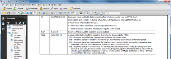
  • Also, what is the difference between mode 2 and mode 3?  What is the purpose of the "reload" registers?  If they are continuous then why the difference?  Also, there seems to be a typo.

  • Brandy,

    I've asked someone to help look into the issue with NDK/timer resouces, but I think I can answer the question about the reload registers.  If you see section 3.9.5 of http://www.ti.com/lit/ug/sprugv5a/sprugv5a.pdf, you'll notice that the timer registers can't be written with an active timer.  So if you ever wanted to change the timer period registers while in continuous mode, you'd have to stop the counter first.  Alternatively, you can write the reload registers while the counter is active and the period registers are automatically loaded with the new values at the point when the counter=period and the counter starts over.

    I see the typo and will have it fixed.

    Hope that helps,

    Travis

  • Hi Brandy

    Could you please upgrade to the latest MCSDK 02_00_09_21, which will install NDK 2.21.00.32, SYS/BIOS 6.33.04.39 and PDK 1.0.0.21, and select these components and build/run your project. That way we can rule out any issues that might have been resolved in these subsequent releases. You can download this latest version of MCSDK from the following link: http://software-dl.ti.com/sdoemb/sdoemb_public_sw/bios_mcsdk/latest/index_FDS.html.

    Once you've verified this, and if the issue persists, could you please attach a zipped folder with your CCS project and all source (.c, .h, and .cfg) files, and I will try to recreate the issues you are seeing, on my setup here, and try to debug.

  • Hi Uday,

    I updated my libraries and still have the same problem.  I can't attach all my code though, unfortunately the project is too far along to be able to hand it away.  I can attach my timer file and most of the init routines since they were written by TI anyhow.  I was able to get the software timer to work under BIOS.  I am ok with the way this is working but I am still baffled by the why the hardware timer doesn't work and I am not sure yet if I will need that accuracy.

    Alternatively, I suppose you could point me to or give me an example of a hardware timer working with the ndk?  With a baseline, I think I could figure out what the problem was.  I mean, I haven't tried this but I think if the ndk "helloworld" example could work with the timers_test.c, then I should be able to do what I want with my application.  The only other point is that my application is multi-core and running from DDR3 and not L2.


    thanks,

    Brandy

    7206.brandysrc.zip

  • Hello Uday,


    Did you get this note?  Any update on why the Hardware timer doesn't work?  I am very intrigued by this interaction.

    Thanks,

    Brandy

  • Hi Brandy

    Yes, I've been looking into it. I was recently able to recreate your issue where when I run the NDK example by itself, it can communicate with a PC client. However, if I run the GP timer test first and then run the NDK code, I can't even ping from a PC client.

    Did you try using a timer other than CSL_TMR_0? We're wondering whether the NDK code somehow tries to use the same timer internally. I am investigating this, but let me know if you have already tried this.

  • yes, I tried timer 8.  I had to rebuild the pdk because the version 17 did not allow for timer8 in its getbaseAddress function, maybe version 21 does now.

    I wasn't sure if I was doing everything right though.


    Thanks,
    brandy

  • Brandy,

    We've further investigated the issue and came to the following conclusions and recommendations:

    Conclusion
    BIOS and CSL, both think that they own the interrupt vector table. Specifically, both are trying to write the ISTP register with a different interrupt vector table address.

    How we came to the conclusion
    In the NDK project, file helloworld.c, we modified main() to be as follows:

    int main()
    {
        intc_init();
        CSL_tmrInit(NULL);
        test_gp_timer(CSL_TMR_8);
        BIOS_start();

    The function int_init calls CSL_intcInit, which in turn calls _CSL_intcIvpSet(). We observed that NDK stops working (6678 doesn't respond to a ping from the PC client) when this function is run, but if we comment out _CSL_intcIvpSet, NDK worked as anticipated and we can ping from the 6678 from a PC client. However, if we do comment this out, the timer timeout interrupt is not received. If you look at the assembly code for _CSL_intcIvpSet we see that it attempts to write the ISTP register with a new interrupt vector table, overwriting what BIOS has already written. The code for _CSL_intcIvpSet is as below:

    __CSL_intcIvpSet:
    bnop b3,2
    mvkl __CSL_intcVectorTable, b0
    mvkh __CSL_intcVectorTable, b0
    mvc b0, istp

    We can confirm this by looking at helloworld_evm6678l.map. Here if you search for the ".csl_vect" section, you'll see that CSL maintains an interrupt vector table in L2. Now if you search for ".vecs" you'll notice that BIOS has setup an interrupt vector table in DDR. So BIOS tries to write this DDR address in ISTP, while CSL tries to write this L2 address in ISTP.

    Recommendations
    Use the BIOS Timer module instead of CSL to setup the timer. Essentially, if you are using BIOS, and there is a BIOS module that can manage hardware/peripheral (including interrupts, timers and cache) then it is recommended that you use the BIOS module. For other hardware/peripherals you can use CSL. You can find details on the Timer, HWI and other modules in the BIOS User's Guide, which is located at C:\ti\bios_6_33_04_39\docs\Bios_User_Guide.pdf.

  • Hello Uday,

    I understand what you mean.  Thank you.

    I would like to follow up about the portion regarding the interrupts where you said to only use the BIOS functionality.  Can you please comment then, what sort of routines I should be using to create interrupts and dispatch plugs etc.  By using multiple TI examples, I think I may have quite the mess on my hands between SRIO, NDK, QMSS, CPPI and Packet Accelerator.  They seem to be slightly unique in how the enable, create and use interrupts and their service routines. 

    My question is similar to the this post:

    http://e2e.ti.com/support/dsp/c6000_multi-core_dsps/f/639/t/199563.aspx

    Thanks,
    Brandy

  • Brandy,

    On the interrupt routines that BIOS provides, I would suggest looking at the BIOS User's Guide, specifically the "Hardware Abstraction Layer" section. This talks about using the HWI module, that provides a collection of APIs for managing hardware interrupts.