This thread has been locked.
If you have a related question, please click the "Ask a related question" button in the top right corner. The newly created question will be automatically linked to this question.
To whom it may concern:
Hi, I'm Eungjun Youn who is currently designing a board with AM3358.
While thoroughly revewing the documents related to AM3358, it turned out that there is no information regarding MDC/MDIO Charateristics.
Could anyone let me know where I can find AM3358 MDC/MIDO Characterictics or send me document containing relevant information?
Your prompt response regarding this request would be highly appreciated.
Thank you for your help in advance.
Yours sincerely,
Eungjun Youn.
Opps! Thanks for bringing this to my attention.
The minimum cycle time for MDC is 400ns.
The minimum low/high pulse duration for MDC is 160ns.
The minimum setup time for MDIO before the rising edge of MDC is 90ns.
The minimum hold time for MDIO after the rising edge of MDC is 0ns.
The minimum output delay for MDIO after the rising edge of MDC is 10ns and the maximum output delay for MDIO after the rising edge of MDC is 390ns.
The maximum transition time for MDC is 5ns.
I will have these parameters added to the next revision of the data sheet.
Regards,
Paul
Thank you for your prompt response.
I have another question regarding the information in your response.
As you mentioned, the minimum cycle time for MDC is 400ns and the maximum output delay for MDIO after the rising edge of MDC is 390ns.
Please confirm again that the information is correct.
If your information is right, I would be having trouble routing on PCB with Ethernet PHY of which Tsetup is 10ns.
I would appreciate it if you could doulbe check the infomation.
Thank you in advance.
Best regards,
Eungjun Youn
The IEEE 802.3 standard defines this time. As you stated the PHY is required to operate with minimum setup time of 10ns. Therefore, the delay from AM335x can not be greater than 390ns to insure the 10ns setup time.
If the maximum output delay is specified to be 390ns, this value represents the worst case delay across all process, voltage, and temperature conditions plus some undefined margin. Most likely, the typical value for this ouptut delay is much less than 390ns.
However, the safe thing to do is design your PCB with a MDIO signal trace shorter than the MDC signal trace. This will add additional margin to the PHY setup time.
Regards,
Paul
Hi Paul,
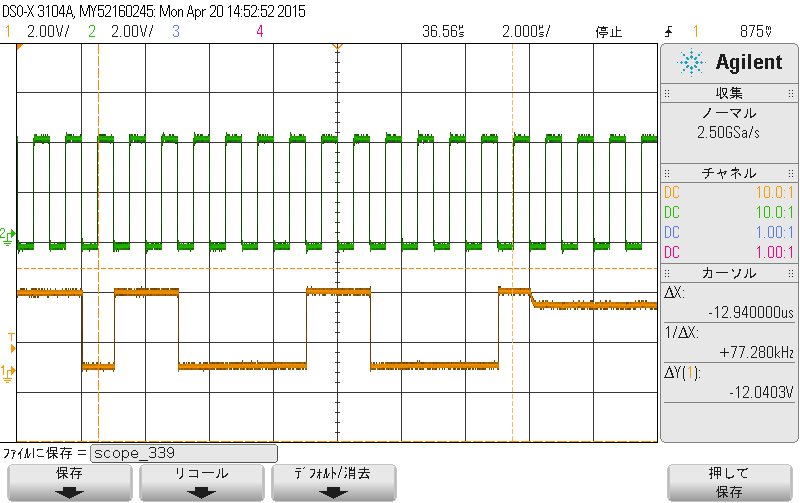
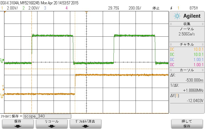
I checked the output delay for MDIO after the rising edge of MDC on the EVM. It was approximately 530nsec.
Does the output delay depend on the MDIO_CLK cycle period?
For the maximum output delay specified to be 390ns in datasheet, what is the condition in the MDIO_CLK cycle period?
Best regards,
Daisuke
Hi Paul,
Thank you for your reply.
I understand that it is the method such as SPI.
I wish the datasheet is updated as soon as possible.
Best regards,
Daisuke