This thread has been locked.

If you have a related question, please click the "Ask a related question" button in the top right corner. The newly created question will be automatically linked to this question.

CC5515 errors when trying to download code with CCS - help needed

Other Parts Discussed in Thread: TMS320C5515

Hello community and happy new year. Wishes for health above all.

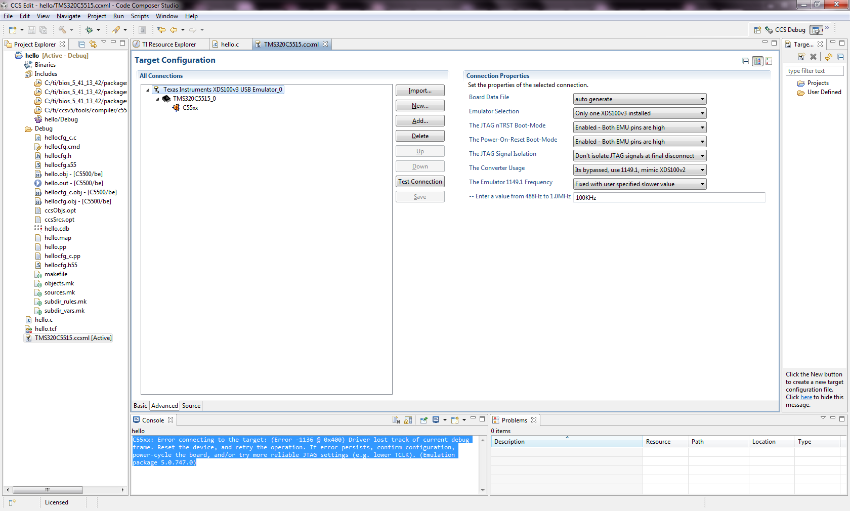
I'm posting because we had problems with one of our designs where we use TMX320VC5515. We tried numerous times to download code using Code Composer Studio with many alternative configurations in the TMS320C5515.ccxml. We are using OLIMEX XDS100v3 debugger. So far the errors got from CCS were of that kind:

Error connecting to the target:
(Error -182 @ 0x0)
The controller has detected a cable break that is near-to itself.
The user must connect the cable/pod to the controller.
(Emulation package 5.0.747.0)


The configuration we used last was

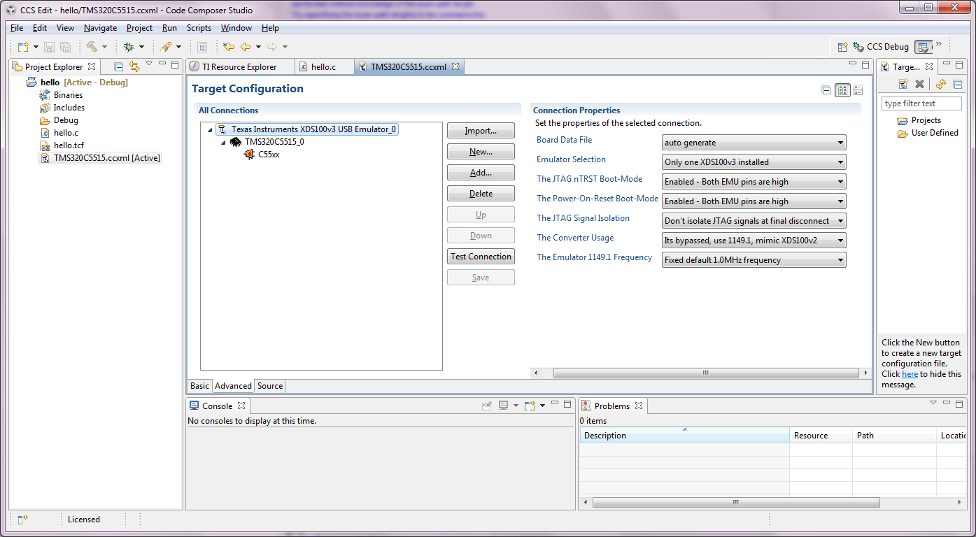
And after clicking Test Connection we got:

[Start]

Execute the command:

%ccs_base%/common/uscif/dbgjtag -f %boarddatafile% -rv -o -F inform,logfile=yes -S pathlength -S integrity

[Result]


-----[Print the board config pathname(s)]------------------------------------

C:\Users\Bluedev\AppData\Local\.TI\213602635\
0\0\BrdDat\testBoard.dat

-----[Print the reset-command software log-file]-----------------------------

This utility has selected a 100- or 510-class product.
This utility will load the adapter 'jioserdesusbv3.dll'.
The library build date was 'May 30 2012'.

The library build time was '22:52:27'.
The library package version is '5.0.747.0'.
The library component version is '35.34.40.0'.
The controller does not use a programmable FPGA.

An error occurred while hard opening the controller.

-----[An error has occurred and this utility has aborted]--------------------

This error is generated by TI's USCIF driver or utilities.

The value is '-183' (0xffffff49).
The title is 'SC_ERR_CTL_CBL_BREAK_FAR'.

The explanation is:
The controller has detected a cable break far-from itself.
The user must connect the cable/pod to the target.

[End]


If anyone could help it would be much appreciated. Thanks in advance.

Nikos

  • Hi Nikos,

    The issue shows that you have issues with the target header connection,

    Try the wiki page: http://processors.wiki.ti.com/index.php?title=Debugging_JTAG_Connectivity_Problems,

    Thanks,

    HR

  • Hello HRi!

    Thnx for the quick response. I looked at the link you posted and found out i had some errors regarding the pinout of the jtag. I followed the instructions that i found and now when i click Test Connection with the options below:

    i get 


    [Start]

    Execute the command:

    %ccs_base%/common/uscif/dbgjtag -f %boarddatafile% -rv -o -F inform,logfile=yes -S pathlength -S integrity

    [Result]


    -----[Print the board config pathname(s)]------------------------------------

    C:\Users\Bluedev\AppData\Local\.TI\213602635\
    0\0\BrdDat\testBoard.dat

    -----[Print the reset-command software log-file]-----------------------------

    This utility has selected a 100- or 510-class product.
    This utility will load the adapter 'jioserdesusbv3.dll'.
    The library build date was 'May 30 2012'.
    The library build time was '22:52:27'.
    The library package version is '5.0.747.0'.
    The library component version is '35.34.40.0'.
    The controller does not use a programmable FPGA.
    The controller has a version number of '4' (0x00000004).
    The controller has an insertion length of '0' (0x00000000).
    This utility will attempt to reset the controller.
    This utility has successfully reset the controller.

    -----[Print the reset-command hardware log-file]-----------------------------

    The scan-path will be reset by toggling the JTAG TRST signal.
    The controller is the FTDI FT2232 with USB interface.
    The link from controller to target is direct (without cable).
    The software is configured for FTDI FT2232 features.
    The controller cannot monitor the value on the EMU[0] pin.
    The controller cannot monitor the value on the EMU[1] pin.
    The controller cannot control the timing on output pins.
    The controller cannot control the timing on input pins.
    The scan-path link-delay has been set to exactly '0' (0x0000).

    -----[The log-file for the JTAG TCLK output generated from the PLL]----------

    Test Size Coord MHz Flag Result Description
    ~~~~ ~~~~ ~~~~~~~ ~~~~~~~~ ~~~~ ~~~~~~~~~~~ ~~~~~~~~~~~~~~~~~~~
    1 512 - 04 27 100.6kHz O good value measure path length
    2 512 - 04 27 100.6kHz [O] good value apply explicit tclk

    There is no hardware for measuring the JTAG TCLK frequency.

    In the scan-path tests:
    The test length was 16384 bits.
    The JTAG IR length was 38 bits.
    The JTAG DR length was 1 bits.

    The IR/DR scan-path tests used 2 frequencies.
    The IR/DR scan-path tests used 100.6kHz as the initial frequency.
    The IR/DR scan-path tests used 100.6kHz as the highest frequency.
    The IR/DR scan-path tests used 100.6kHz as the final frequency.

    -----[Measure the source and frequency of the final JTAG TCLKR input]--------

    There is no hardware for measuring the JTAG TCLK frequency.

    -----[Perform the standard path-length test on the JTAG IR and DR]-----------

    This path-length test uses blocks of 512 32-bit words.

    The test for the JTAG IR instruction path-length succeeded.
    The JTAG IR instruction path-length is 38 bits.

    The test for the JTAG DR bypass path-length succeeded.
    The JTAG DR bypass path-length is 1 bits.

    -----[Perform the Integrity scan-test on the JTAG IR]------------------------

    This test will use blocks of 512 32-bit words.
    This test will be applied just once.

    Do a test using 0xFFFFFFFF.
    Scan tests: 1, skipped: 0, failed: 0
    Do a test using 0x00000000.
    Scan tests: 2, skipped: 0, failed: 0
    Do a test using 0xFE03E0E2.
    Scan tests: 3, skipped: 0, failed: 0
    Do a test using 0x01FC1F1D.
    Scan tests: 4, skipped: 0, failed: 0
    Do a test using 0x5533CCAA.
    Scan tests: 5, skipped: 0, failed: 0
    Do a test using 0xAACC3355.
    Scan tests: 6, skipped: 0, failed: 0
    All of the values were scanned correctly.

    The JTAG IR Integrity scan-test has succeeded.

    -----[Perform the Integrity scan-test on the JTAG DR]------------------------

    This test will use blocks of 512 32-bit words.
    This test will be applied just once.

    Do a test using 0xFFFFFFFF.
    Scan tests: 1, skipped: 0, failed: 0
    Do a test using 0x00000000.
    Scan tests: 2, skipped: 0, failed: 0
    Do a test using 0xFE03E0E2.
    Scan tests: 3, skipped: 0, failed: 0
    Do a test using 0x01FC1F1D.
    Scan tests: 4, skipped: 0, failed: 0
    Do a test using 0x5533CCAA.
    Scan tests: 5, skipped: 0, failed: 0
    Do a test using 0xAACC3355.
    Scan tests: 6, skipped: 0, failed: 0
    All of the values were scanned correctly.

    The JTAG DR Integrity scan-test has succeeded.

    [End]


    Which is good! (i guess)

    But when i try to Debug with that configuration i get the message:

    C55xx: Error connecting to the target: (Error -1136 @ 0x400) Driver lost track of current debug frame. Reset the device, and retry the operation. If error persists, confirm configuration, power-cycle the board, and/or try more reliable JTAG settings (e.g. lower TCLK). (Emulation package 5.0.747.0)

    I tried lower TCLK as you may see from the test above(100kHz) but i still get the same error message. Do you have any tips on this? Thanks again.

    Nikos

  • Hello again and thanks a lot for your help!

    I put the oscilator to monitor the signals of the JTAG header and i saw that when clicking Test Connection everything seems ok, BUT when clicking Debug signal TRSTn doesnt go LOW!!! What could be the problem here????Thanks again

    Nikos

  • Nikos,

    Please check "JTAG and nTRST Special Considerations (includes TMS and TDI) " at http://processors.wiki.ti.com/index.php/XDS_Target_Connection_Guide#JTAG_and_nTRST_Special_Considerations_.28includes_TMS_and_TDI.29

    Thanks,

    HR

  • HRi hello again! Thanks again for your reply.

    I've previously checked this chapter and done all the needed configurations. 

    The problem is that:

    When clicking Test Connection everything works OK and TRST acts like it is supposed to act. But when clicking Debug TRST is stuck at '1'. Why in test mode everything works and when trying to debug this happens? 

  • Hi Nikos,

    I don't think your issue is TRST as it is used during test/reset, do you have another board to check?

    Thanks,

    HR

  • Hello HRi,

    I recently got my hands again on the board. I wanted to thank you for all your help. It seems that the final step should be the step mentioned in the thread you posted above(last post). I will try it and let you know. Thank you

    Nikos