This thread has been locked.

If you have a related question, please click the "Ask a related question" button in the top right corner. The newly created question will be automatically linked to this question.

6678EVM communication with Xilinx K7 develeopment through SRIO

Other Parts Discussed in Thread: TMS320C6670

hello,I‘m using 6678EVM to communicate with Xilinx K7 platform ,now I have some problem as follow,

description:

test platform : 6678EVM and Xilinx K7

test code :the SRIO test code for 6678 is downloaded from TI chinese forum "http://www.deyisupport.com/",and the test code for K7 is generated from IP CORE

question :

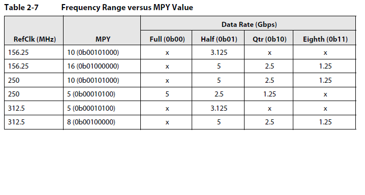
1.The SRIO speed is set to  5Gbps,and the reference clock for SRIO on 6678 is 312.5MHz, while it is 125MHz on Xilinx K7,does it matter that they doesn't equal?

2.In my test ,the DSP is slave ,and FPGA is master, when I run the program on dsp,I see a print message which is "the dsp is ready for test",but how can I make sure that it has been woring right.

3.When I readthe code for DSP ,In digital loopback mode, I see the DSP is configured as processor,but I tried to change it to memory and bridge ,it also works right(because I see the print message show that the test is complete ),does it any difference among processor ,memory,switch and bridge; In my opinion,you should configure this parameter by the type of the SRIO device ,so the 6678 can only be configured as processor ,otherwise, it surely doesn't work, and I think a SRIO device which is configured as memory can't issue any request ,it can only receive request , does my comprehension right, waiting for your answer,thank you!

  • 1) No it doesn't matter that the refclk frequencies are different, only that the jitter is within spec.

    2) I'm unfamiliar with the code you reference, but assuming that you are getting port_ok set in the status register and your ackids are aligned, it should be able to receive packets.

    3) Don't worry about the processor/memory/bridge, it has no effect.  You said test completed, not sure if it passed or not, not sure I understand the issue.  Hopefully you are getting support from DEYI.

    Regards,

    Travis

  • The example you got was demo for loopback in one DSP, or data transfer between two DSPs. You can modify following code to change the test mode:

    SRIO_Loopback_Mode loopback_mode= SRIO_NO_LOOPBACK;

    SRIO_NO_LOOPBACK means data transfer between DSPs, that is the mode close to your test.

    This test runs one DSP as slave and the other as master which is determined by the "uiDspNum" in following code:

     else if(SRIO_NO_LOOPBACK==loopback_mode)  //test between 2 DSPs
     {
      /*DSP0 is the master for test, DSP0 DirectIO or send message to DSP1.
      DSP1 is the slave for test, it monitor the doorbell and message
      interrupt to detect the received data*/
      if(0==uiDspNum)
      {
       SRIO_2DSP_Test();
      }
      else
      {

    ......

    Since in your test, you want to run the DSP as slave, you need set the uiDspNum=1 before above code.

    And, you need modify other configurations based on your case, which may include device ID, speed, lane combination...


  • Thanks for your help, the code you show is exactly I used for test ,and I have changed the seetings above .In my test,first ,I change the mode from SRIO_DIGITAL_LOOPBACK to SRIO_NO_LOOPBACK,second ,I change the code "if(0==uiDspNum)" to "if(1==uiDspNum)",then I run the program,I see the print show that "DSP1 ready as slave for test",and I check the SP_ERR_STAT is 0x00000302,which meas that the port is OK,but the input error stop happens,when I read the code as follow:
    if(1==uiDspNum)
    {
    SRIO_2DSP_Test();
    }
    else
    {
    srio_cfg.device_ID_routing_config= dsp1_device_ID_routing_config;
    srio_cfg.uiNumDeviceId=
    sizeof(dsp1_device_ID_routing_config)/
    sizeof(SRIO_Device_ID_Routing_Config);

    msg_cfg.message_map = DSP1_message_map;
    msg_cfg.uiNumMessageMap=
    sizeof(DSP1_message_map)/sizeof(SRIO_RX_Message_Map);
    srio_cfg.msg_cfg= &msg_cfg;

    serdesLinkSetup.linkSpeed_GHz= SRIO_DEFAULT_TEST_SPEED;
    srio_cfg.srio_1x2x4x_path_control= SRIO_PATH_CTL_1xLaneA_1xLaneB_1xLaneC_1xLaneD;
    srio_identify_used_ports_lanes(srio_cfg.srio_1x2x4x_path_control);

    /*On Turbo Nyquist EVM only lane 2 and 3 are connected between 2 DSPs*/
    srio_cfg.blockEn.bLogic_Port_EN[0]= FALSE;
    srio_cfg.blockEn.bLogic_Port_EN[1]= FALSE;

    Keystone_SRIO_Init(&srio_cfg);
    SRIO_PktDM_init();

    /*accumulation is only used for the 2nd DSP for two DSPs test*/
    QMSS_Accumulation_config();

    puts("DSP1 ready as slave for test");
    while(1);
    }
    I found a problem with the code above,it seems that the code can't test Direct I/O packet if uiDspNum equals to 0,because of that the item “lsu_cfg” in srio_cfg didn't configured , it can only test message packet? furthermore,if I run this code on 6678, do I need to comment the code bellow:
    srio_cfg.blockEn.bLogic_Port_EN[0]= FALSE;
    srio_cfg.blockEn.bLogic_Port_EN[1]= FALSE;
    because I connect all the 4 ports with K7, waitting for your reply ,thank you very much!

  • Again, I can't help on the code example, but if you are stuck in input or output error stopped state (while Port_ok), they you need to follow the proceedure in the Keystone Software Error recovery to exit this state.  check out...

    http://e2e.ti.com/support/dsp/c6000_multi-core_dsps/f/639/p/167620/619318.aspx#619318

    Regards,

    Travis

  • Yes, you should enable lane 0 and 1 if you need them in your test.

    LSU model is only for TX of DirectIO. If the DSP is slave for DirectIO test, you do not need configure the LSU.

  • Thanks for your help,as you said above, if I configure the DSP as slave ,although I didn't configure the LSU, it also can be used to test Direct I/O, and I must configure the LSU if I configure the DSP as master, does it right?

          Now I have some other problem confused me,first, if the SP_ERR_STAT show that the port is OK, can I say that the physic connection is OK?

    second, in my test,if I configure the speed as 5.0Gbps, both the DSP and FPGA can be initialized, and the PORT is ok,but if I configure the speed as 1.25Gbps by change the code as bellow, the FPGA initialize state line become unstable, it changes from '1' to '0'   randomly, which is the reason for this ,should I configue something else?

    change #define SRIO_DEFAULT_TEST_SPEED 5.0 to #define SRIO_DEFAULT_TEST_SPEED 1.25

    I'll waiting for your reply ,sincerely yours黄成章!!!~_~

  • "Port OK" is one of the key flag, but it does not indicate all right. It is possible that "Port OK" is set, but there are still other error. The "SRIO_debug.c" provides functions to check all status/flags.

    For 1.25GHz issue, firstly, please check if the Serdes PLL is configured as 312.5MHz*8/2=1.25GHz. In our early example, it may be configured as  312.5MHz*16/1=1.25GHz, which is incorrect, because the Serdes PLL output must be between 1.5625 and 3.125, and, the link rate scale should be used to achieve final expected link rate. Attached please find updated code for Serdes configuration:

    /******************************************************************************
    
      Copyright (C), 2001-2012, Texas Instrument.
    
     ******************************************************************************
      File Name     : KeyStone_Serdes_init.c
      Version       : Initial Draft
      Author        : Brighton
      Created       : 2011/6/10
      Last Modified :
      Description   :  example for Serdes configuration on KeyStone DSP
    
      Function List :
                  KeyStone_HyperLink_Serdes_init
                  KeyStone_Serdes_disable
                  KeyStone_SGMII_Serdes_init
                  KeyStone_SRIO_Serdes_init
      History       :
      1.Date        : 2011/6/10
        Author      : Brighton
        Modification: Created file
    
      2.Date         : 2011/6/13
        Author       : Zhan
        Modification : Modify the SRIO SERDES configuration
    
    ******************************************************************************/
    #include "KeyStone_Serdes_init.h"
    /*----------------------------------------------*
     * external variables                           *
     *----------------------------------------------*/
    
    /*----------------------------------------------*
     * external routine prototypes                  *
     *----------------------------------------------*/
    
    /*----------------------------------------------*
     * internal routine prototypes                  *
     *----------------------------------------------*/
    
    /*----------------------------------------------*
     * project-wide global variables                *
     *----------------------------------------------*/
    
    /*----------------------------------------------*
     * module-wide global variables                 *
     *----------------------------------------------*/
    
    /*----------------------------------------------*
     * constants                                    *
     *----------------------------------------------*/
    
    /*----------------------------------------------*
     * macros                                       *
     *----------------------------------------------*/
    
    /*----------------------------------------------*
     * routines' implementations                    *
     *----------------------------------------------*/
    /*****************************************************************************
     Prototype    : KeyStone_SRIO_Serdes_init
     Description  : Configure the SRIO SERDES
     Input        : SerdesSetup_4links * serdes_cfg  
                    SerdesRegs * serdesRegs          
     Output       : None
     Return Value : 
     Calls        : 
     Called By    : 
     
      History        :
      1.Date         : 2011/6/11
        Author       : Brighton
        Modification : Created function
    
      2.Date         : 2011/6/13
        Author       : Zhan
        Modification : Add the status check
    *****************************************************************************/
    void KeyStone_SRIO_Serdes_init(
    	SerdesSetup_4links * serdes_cfg, SerdesRegs * serdesRegs)
    {
    	int i;
    	float pllMpy, serdesPllClock_GHz=12.5, rateScale;
    	SerdesLinkRate linkRateScale; 
    	SerdesVcoRange vcoRange;
    
    	if(NULL== serdes_cfg)
    		return;
    		
    	CSL_BootCfgUnlockKicker();
    
    	/*find lowest link speed, the SERDES PLL output should be less or equal to it*/
    	for(i= 0; i<4; i++)
    	{
    		if(serdes_cfg->linkSetup[i])
    			if(serdesPllClock_GHz>serdes_cfg->linkSetup[i]->linkSpeed_GHz)
    				serdesPllClock_GHz=serdes_cfg->linkSetup[i]->linkSpeed_GHz;
    	}
    
    	/*Serdes PLL output must be between 1.5625 and 3.125*/
    	if(serdesPllClock_GHz>6.25)
    		serdesPllClock_GHz /= 4;
    	else if(serdesPllClock_GHz>3.125)
    		serdesPllClock_GHz /= 2;
    	else if(serdesPllClock_GHz<1.5625)
    		serdesPllClock_GHz *= 2;
    
    	/*set VCO range according to the PLL output speed*/
    	if(serdesPllClock_GHz<2.17)
    		vcoRange= SERDES_PLL_VCO_RANGE_HIGH;
    	else
    		vcoRange= SERDES_PLL_VCO_RANGE_LOW;
    
    	/*calculate PLL MPY factor according to input reference clock speed*/
    	pllMpy= serdesPllClock_GHz*1000/serdes_cfg->commonSetup.inputRefClock_MHz;
    
    	/*PLL multiply factors between 4 and 60*/
    	if(pllMpy<4 || pllMpy>60)
    		pllMpy= 4;
    
    	serdesRegs->CFGPLL = 1| /*ENPLL*/
    		(serdes_cfg->commonSetup.loopBandwidth<<11)|
    		(vcoRange<<9)|
    		((Uint32)(pllMpy*4)<<1);
    
    	for(i=0; i<4; i++)
    	{
    		if(serdes_cfg->linkSetup[i])
    		{
    			rateScale=serdes_cfg->linkSetup[i]->linkSpeed_GHz/serdesPllClock_GHz;
    			if(rateScale<1)
    				linkRateScale = SRIO_SERDES_LINK_RATE_div2;
    			else if(rateScale<2)
    				linkRateScale = SRIO_SERDES_LINK_RATE_x1;
    			else if(rateScale<4)
    				linkRateScale = SRIO_SERDES_LINK_RATE_x2;
    			else
    				linkRateScale = SRIO_SERDES_LINK_RATE_x4;
    				
    			serdesRegs->link[i].CFGRX= 1| /*ENRX*/
    				(2<<1)| 	/*Bus width must be 010b (20 bit)*/
    				(serdes_cfg->linkSetup[i]->testPattern<<25)|
    				(serdes_cfg->linkSetup[i]->loopBack<<23)|
    				(1<<22)| 	/*Enable offset compensation*/
    				(serdes_cfg->linkSetup[i]->rxEqualizerConfig<<18)|
    				(serdes_cfg->linkSetup[i]->rxCDR<<15)|
    				(serdes_cfg->linkSetup[i]->rxLos<<12)|
    				(serdes_cfg->linkSetup[i]->rxAlign<<10)|
    				(serdes_cfg->linkSetup[i]->rxTermination<<7)|
    				(serdes_cfg->linkSetup[i]->rxInvertPolarity<<6)|
    				(linkRateScale<<4);
    
    			if(i==0)
    				serdesRegs->link[i].CFGTX= 1| /*ENTX*/
    					(2<<1)| 	/*Bus width must be 010b (20 bit)*/
    					(serdes_cfg->linkSetup[i]->testPattern<<23)|
    					(serdes_cfg->linkSetup[i]->loopBack<<21)|
    					(1 << 20)| 	/*Synchronization Master.*/
    					(serdes_cfg->linkSetup[i]->txOutputSwing<<7)|
    					(serdes_cfg->linkSetup[i]->txInvertPolarity<<6)|
    					(linkRateScale<<4);
    			else
    				serdesRegs->link[i].CFGTX= 1| /*ENTX*/
    					(2<<1)| 	/*Bus width must be 010b (20 bit)*/
    					(serdes_cfg->linkSetup[i]->testPattern<<23)|
    					(serdes_cfg->linkSetup[i]->loopBack<<21)|
    					(0 << 20)| 	/*Synchronization Master.*/
    					(serdes_cfg->linkSetup[i]->txOutputSwing<<7)|
    					(serdes_cfg->linkSetup[i]->txInvertPolarity<<6)|
    					(linkRateScale<<4);
    		}
    	}
    
    }
    /*****************************************************************************
     Prototype    : KeyStone_HyperLink_Serdes_init
     Description  : Hyperlink SERDES configuration
     Input        : SerdesSetup_4links * serdes_cfg  
                    SerdesRegs * serdesRegs          
     Output       : None
     Return Value : 
     Calls        : 
     Called By    : 
     
      History        :
      1.Date         : 2011/6/11
        Author       : Brighton
        Modification : Created function
    
    *****************************************************************************/
    void KeyStone_HyperLink_Serdes_init(
    	SerdesSetup_4links * serdes_cfg, SerdesRegs * serdesRegs)
    {
    	int i;
    	float pllMpy, serdesPllClock_GHz=12.5, rateScale;
    	SerdesLinkRate linkRateScale; 
    	SerdesVcoRange vcoRange;
    
    	if(NULL== serdes_cfg)
    		return;
    		
    	CSL_BootCfgUnlockKicker();
    
    	/*find lowest link speed, the SERDES PLL output should be less or equal to it*/
    	for(i= 0; i<4; i++)
    	{
    		if(serdes_cfg->linkSetup[i])
    			if(serdesPllClock_GHz > serdes_cfg->linkSetup[i]->linkSpeed_GHz)
    				serdesPllClock_GHz = serdes_cfg->linkSetup[i]->linkSpeed_GHz;
    	}
    
    	/*Serdes PLL output must be less than 3.125*/
    	if(serdesPllClock_GHz>6.25)
    		serdesPllClock_GHz /= 4;
    	else if(serdesPllClock_GHz>3.125)
    		serdesPllClock_GHz /= 2;
    	else if(serdesPllClock_GHz<1.5625)
    		serdesPllClock_GHz *= 2;
    
    	/*set VCO range according to the PLL output speed*/
    	if(serdesPllClock_GHz<2.17)
    		vcoRange= SERDES_PLL_VCO_RANGE_HIGH;
    	else
    		vcoRange= SERDES_PLL_VCO_RANGE_LOW;
    
    	/*calculate PLL MPY factor according to input reference clock speed*/
    	pllMpy= serdesPllClock_GHz*1000/serdes_cfg->commonSetup.inputRefClock_MHz;
    
    	/*PLL multiply factors between 4 and 60*/
    	if(pllMpy<4 || pllMpy>60)
    		pllMpy= 4;
    
    	for(i=0; i<4; i++)
    	{
    		if(serdes_cfg->linkSetup[i])
    		{
    			rateScale=serdes_cfg->linkSetup[i]->linkSpeed_GHz/serdesPllClock_GHz;
    			if(rateScale<1)
    				linkRateScale = HYPERLINK_SERDES_LINK_RATE_div2;
    			else if(rateScale<2)
    				linkRateScale = HYPERLINK_SERDES_LINK_RATE_x1;
    			else if(rateScale<4)
    				linkRateScale = HYPERLINK_SERDES_LINK_RATE_x2;
    			else
    				linkRateScale = HYPERLINK_SERDES_LINK_RATE_x4;
    
    			/*Serdes Loopback is controled by Hyperlink control
    			register, Serdes loopback register has no effect*/
    			/*HyperLink automatically sets LOS to 0 for loopback. 
    			User must set LOS to 4 for non-loopack*/
    			serdes_cfg->linkSetup[i]->rxLos = (SerdesRxLos)4;
    
    			serdesRegs->link[i].CFGRX= 1| /*ENRX*/
    				(2<<1)| 	/*Bus width must be 010b (20 bit)*/
    				(serdes_cfg->linkSetup[i]->testPattern<<25)|
    				(1<<22)| 	/*Enable offset compensation*/
    				(serdes_cfg->linkSetup[i]->rxEqualizerConfig<<18)|
    				(serdes_cfg->linkSetup[i]->rxCDR<<15)|
    				(serdes_cfg->linkSetup[i]->rxLos<<12)|
    				(serdes_cfg->linkSetup[i]->rxAlign<<10)|
    				(serdes_cfg->linkSetup[i]->rxTermination<<7)|
    				(serdes_cfg->linkSetup[i]->rxInvertPolarity<<6)|
    				(linkRateScale<<4);
    
    			serdesRegs->link[i].CFGTX= 1| /*ENTX*/
    				(2<<1)| 	/*Bus width must be 010b (20 bit)*/
    				(serdes_cfg->linkSetup[i]->testPattern<<23)|
    				(serdes_cfg->linkSetup[i]->loopBack<<21)|
    				(1 << 20)| 	/*Synchronization Master.*/
    				(1<<19)| 	/*FIRUPT = 1 Transmitter pre and post cursor FIR filter update*/
    				/*TWPST1: Adjacent Post Cursor Tap Weight. 
    				If trace length is 4��, start with 20 (-10%). 
    				If trace length is between 4�� and 10��, start with 27 (-27.5%).*/
    				(18<<14)| 	
    				(1<<11)| 	/*TWPRE: The settings range from 0 to -17.5% in 2.5% steps.*/
    				(serdes_cfg->linkSetup[i]->txOutputSwing<<7)|
    				(serdes_cfg->linkSetup[i]->txInvertPolarity<<6)|
    				(linkRateScale<<4);
    		}
    	}
    
    	/*write to CFGPLL will start the Hyperlink training sequence, so, 
    	this should be the last register been write for HyperLink initialization*/
    	serdesRegs->CFGPLL = 1| /*ENPLL*/
    		(serdes_cfg->commonSetup.loopBandwidth<<11)|
    		(vcoRange<<9)|
    		((Uint32)(pllMpy*4)<<1);
    
    }
    
    /*****************************************************************************
     Prototype    : KeyStone_Serdes_disable
     Description  : SERDES disable for KeyStone device
     Input        : SerdesRegs * serdesRegs  
                    Uint32 uiLinkNum         
     Output       : None
     Return Value : 
     Calls        : 
     Called By    : 
     
      History        :
      1.Date         : 2011/6/13
        Author       : Brighton
        Modification : Created function
    
    *****************************************************************************/
    void KeyStone_Serdes_disable(
    	SerdesRegs * serdesRegs, Uint32 uiLinkNum)
    {
    	int i;
    	
    	CSL_BootCfgUnlockKicker();
    
    	//disable PLL
    	serdesRegs->CFGPLL = 0;
    
    	//disable TX/RX links
    	for(i= 0; i< uiLinkNum; i++)
    	{
    		serdesRegs->link[i].CFGRX= 0;
    		serdesRegs->link[i].CFGTX= 0;
    	}
    }


    If above configuration is correct, then, you may need fine tune some TX and RX configuration, such as, emphasize, adaption.. You may need adjust them according to the eye diagram you observed with oscilloscope.


  • Thank you ,maybe I should make sure the physical connection is right and stable ,but I have no idea to prove it ,do you have any advice I should take to make sure the physical connection is right .To SRIO, is there a standard procedure to test it step by step,for example," first,you should ....,an then check the ....;second, you should..., and then check the ...;......, finally,  .....". wishing your answer, thank you !

  • I suggest you check the eye-diagram firstly.

    Thank you!

  • Thanks for your help! Now,I  have another problem, today, I compare the KeyStone_SRIO_Serdes_init function between I used and the code you give me, I just find one difference as follow:

    /*Serdes PLL output must be between 1.5625 and 3.125*/
    if(serdesPllClock_GHz>6.25)
    serdesPllClock_GHz /= 4;
    else if(serdesPllClock_GHz>3.125)
    serdesPllClock_GHz /= 2;
    else if(serdesPllClock_GHz<1.5625)
    serdesPllClock_GHz *= 2;

    in my test code ,there is no "serdesPllClock_GHz *= 2;",and I tried to add it,but I fiind another problem as follow:

    void KeyStone_SRIO_Serdes_init(
    SerdesSetup_4links * serdes_cfg, SerdesRegs * serdesRegs)
    {
    int i;
    float pllMpy, serdesPllClock_GHz=12.5, rateScale;
    SerdesLinkRate linkRateScale;
    SerdesVcoRange vcoRange;

    if(NULL== serdes_cfg)
    return;

    CSL_BootCfgUnlockKicker();

    /*find lowest link speed, the SERDES PLL output should be less or equal to it*/
    for(i= 0; i<4; i++)
    {
    if(serdes_cfg->linkSetup[i])
    if(serdesPllClock_GHz>serdes_cfg->linkSetup[i]->linkSpeed_GHz)
    serdesPllClock_GHz=serdes_cfg->linkSetup[i]->linkSpeed_GHz;
    }

    /*Serdes PLL output must be between 1.5625 and 3.125*/
    if(serdesPllClock_GHz>6.25)
    serdesPllClock_GHz /= 4;
    else if(serdesPllClock_GHz>3.125)
    serdesPllClock_GHz /= 2;
    else if(serdesPllClock_GHz<1.5625)
    serdesPllClock_GHz *= 2;

    if I set serdes_cfg->linkSetup[0-4] to 1.25,then after the code above run ,the value of serdesPllClock_GHz is 1.25*2 = 2.5,then I continue run  the code until the code bellow,

    for(i=0; i<4; i++)
    {
    if(serdes_cfg->linkSetup[i])
    {
    rateScale=serdes_cfg->linkSetup[i]->linkSpeed_GHz/serdesPllClock_GHz;

    if(rateScale<1)
    linkRateScale = SRIO_SERDES_LINK_RATE_div2;
    else if(rateScale<2)
    linkRateScale = SRIO_SERDES_LINK_RATE_x1;
    else if(rateScale<4)
    linkRateScale = SRIO_SERDES_LINK_RATE_x2;
    else
    linkRateScale = SRIO_SERDES_LINK_RATE_x4;

    after the code above executed, the value of linkRateScale is 0x11, and I find the value seemly  undefined according to the document(SPRUGW1A) on page 43 and page 46,on page 43 ,it said that if the ratescale is 0x03, it is eighth rate,while it is reserved for 0x03 on page 46,this confused me ,how could I set the serdes PLL? I think I should just configue the "serdes_cfg->CFG_PLL.MPY = 8" and set the RATE bit in "serdesRegs->link[i].CFGRX" or "serdesRegs->link[i].CFGTX" as 0x11 according to the tabel 2-7 on page 43 in SRUGW1A, but it seems that it is wrong if I do that, it seems that it can't run as 1.25Gbps on 6678EVM
    because of the refclock is 312.5MHz, does it right?


  • You were looking at old document, below is the updated information in the new version of the document (sprugw1b):

    00 Full Rate Four data samples taken per PLL output clock cycle
    01 Half Rate Two data sample taken per PLL output clock cycle
    10 Quarter Rate One data sample taken per PLL output clock cycle
    11 Eighth Rate One data sample taken every two PLL output clock cycles

  • Now, I have some other problem ,and it is descripted in the attached document bellow, Can you help me,thank you!

    5280.SRIO detail .docx

  • hi,

    It seems that we are facing the same questions. Our research group are trying to use SRIO port through AMC socket to set up communication between FPGA Stratix IV and TI's DSP TMS320C6670. Currently, the port_ok bit in SP_ERR_STAT will change when FPGA initialize its SRIO port, which means we can continue with ACK_ID aligning and  packet sending. However, in my opinion, FPGA does not have LSU and some other buffer so that we cannot use the example given by TI which expects to build up linking with two dsps. I am trying to modify the code in SRIO_2DSP_TEST, if you have some good news, please tell me. Thank you so much.

    Best regards,

    Shuyang Hua.

    Email: huasy123@gmail.com

    Tel:86-15873232016