This thread has been locked.

If you have a related question, please click the "Ask a related question" button in the top right corner. The newly created question will be automatically linked to this question.

u-boot "reset" command hangs

Other Parts Discussed in Thread: OMAP-L138, OMAPL138

Hi,

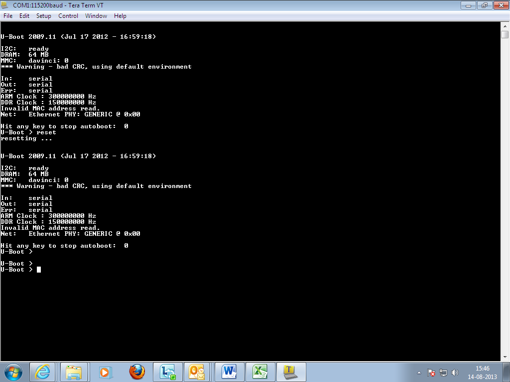
I am working with OMAP-L138.

"reset" command of u-boot hangs. It does not reset the processor.

The reset code looks like it should work (I am attaching the code which is in u-boot below). Can anybody give me any suggestions to try?

Cheers,

-raja.

.globl reset_cpu
reset_cpu:
ldr r0, WDT_TGCR
mov r1, $0x08
str r1, [r0]
ldr r1, [r0]
orr r1, r1, $0x03
str r1, [r0]
mov r1, $0
ldr r0, WDT_TIM12
str r1, [r0]
ldr r0, WDT_TIM34
str r1, [r0]
ldr r0, WDT_PRD12
str r1, [r0]
ldr r0, WDT_PRD34
str r1, [r0]
ldr r0, WDT_TCR
ldr r1, [r0]
orr r1, r1, $0x40
str r1, [r0]
ldr r0, WDT_WDTCR
ldr r1, [r0]
orr r1, r1, $0x4000
str r1, [r0]
ldr r1, WDTCR_VAL1
str r1, [r0]
ldr r1, WDTCR_VAL2
str r1, [r0]
/* Write an invalid value to the WDKEY field to trigger
* an immediate watchdog reset */
mov r1, $0x4000
str r1, [r0]
nop
nop
nop

nop
reset_cpu_loop:
b reset_cpu_loop

WDT_TGCR:
.word 0x01c21c24
WDT_TIM12:
.word 0x01c21c10
WDT_TIM34:
.word 0x01c21c14
WDT_PRD12:
.word 0x01c21c18
WDT_PRD34:
.word 0x01c21c1c
WDT_TCR:
.word 0x01c21c20
WDT_WDTCR:
.word 0x01c21c28
WDTCR_VAL1:
.word 0xa5c64000
WDTCR_VAL2:
.word 0xda7e4000

  • Hi,

    When I tested the u-boot ( pre-built u-boot binary with version:- U-Boot 2009.11 (Jul 17 2012 - 16:59:18)), on OMAPL138 SDI EVM, it performs the reset without any problem. Attached the snapshot below for reference.

    If you have the OMAPL138 EVM and if needed I can upload the pre-built binary, so that you can give it a try on EVM.

    Please clarify the following.

    1. What is the version of u-boot used? Is it a part of Davinci PSP? If yes, specify the version of PSP.

    2. Did you customize the u-boot source code or Is it a pre-built u-boot binary?

    3. Are you trying directly on custom board based on OMAPL138? or a trial run on EVMS / LCDK? If on EVMS, Is it from Logic PD or spectrum Digital?


    Regards,

    Shankari


    -------------------------------------------------------------------------------------------------------

    Please click the Verify Answer button on this post if it answers your question.
    --------------------------------------------------------------------------------------------------------

  • Thank you Shankari.

    1. I am using the u-boot in PSP 03.22.00.02

    2. It is customized for our design. So, it is built from scratch. I build u-boot.ais and program it to SPI flash and run it from there

    3. I am trying it directly on the custom board.

    Question:

    From what I can read, it appears as if watchdog is all internal to the chip. Is that correct? There is no external signals needed to trigger a chip reset. Is that correct?

    Cheers,

    -raja.

  • Hi Raja,

    Thanks for your update.

    Basically Timer module is a CPU/Device peripheral and its implementation have signal connections to internal device reset which can be used in watchdog timer mode and generates output event to device reset. The timer can be configured as a watchdog timer using the timer mode (TIMMODE) bit in the timer global control register (TGCR) and the watchdog timer enable (WDEN) bit in the watchdog timer control register (WDTCR).

    In order to address your above questions as below:

    The timer module should be internally connected to the device hardware reset signal in order to fully function in watchdog timer mode. So, this answers your first question that, timer in watchdog mode is all completely internal to the chip. Watchdog timer module is actually sourcing the wake-up interrupt for the device to wake up and should not be disabled. A watchdog reset actually triggers a power-on-reset (POR) of the device. Please refer Section 31.2.2 in the OMAPL138 TRM as below:

    http://www.ti.com/lit/ug/spruh77a/spruh77a.pdf

    To answer your second question, there are no external signals needed to trigger a chip reset and only the watchdot timer internally resets the device chip.

    Thanks & regards,

    Sivaraj K

    ---------------------------------------------------------------------------------
    Please click the
    Verify Answer button on this post if it answers your question.
    ---------------------------------------------------------------------------------


  • Thank you Sivaraj.

    I am not sure what the following means exactly. Does that mean I need to enable an interrupt and possibly I have it turned off in my code?

    ********************
    Watchdog timer module is actually sourcing the wake-up interrupt for the device to wake up and should not be disabled
    ********************

    Can you please clarify? Also, any suggestions on what I can check?

    Cheers,

    -raja. 

  • Hi Raja,

    I apologise for the misinterpretation.

    ********************
    Watchdog timer module is actually sourcing the wake-up interrupt for the device to wake up and should not be disabled
    ********************

    I intend to say the above statement in general and it doesn't apply to your code. By default, the wake-up interrupt will be enabled for the device to exit from WFI mode (Wait for Interrupt) to wake up and actually, the watchdog timer module sends (sources) the wake-up interrupt to the device to turn on from sleep mode.

    Thanks for your understanding.

    Regards,

    Sivaraj K

    ---------------------------------------------------------------------------------
    Please click the
    Verify Answer button on this post if it answers your question.
    ---------------------------------------------------------------------------------
     
  • Thank you Sivaraj.

    Is there anything I can try to get a better understanding of the problem? Maybe look at some registers?

    So far, nothing has been directing me towards the problem

  • Hi,

    Did you try debugging the customized u-boot source code using CCS?

    Give it a try with this link http://processors.wiki.ti.com/index.php/U-boot_Debug_in_CCSv5


    Regards,

    Shankari

  • Hi Raja,

    Please below steps may help you to solve the u-boot reset issue (enable reset command in u-boot).

    1. Please enable the CONFIG_HW_WATCHDOG macro in configuration header file(include/configs/xxx.h).

    Reference: uboot-03.22.00.02/include/configs/calimain.h

    2. Init the watchdog using davinci_hw_watchdog_enable() from board_init() routine. (board/boardxx.c)

    #ifdef CONFIG_HW_WATCHDOG
    davinci_hw_watchdog_enable();
    #endif

    3. Enable the hw_watchdog_reset() routine to call davinci_hw_watchdog_reset().

    #ifdef CONFIG_HW_WATCHDOG
    void hw_watchdog_reset(void)
    {
    davinci_hw_watchdog_reset();
    }
    #endif

    Reference: uboot-03.22.00.02/board/omicron/calimain/calimain.c

    4. Rebuild and test the u-boot with generated u-boot file.

    Watchdog source in uboot-03.22.00.02:

    uboot-03.22.00.02/arch/arm/cpu/arm926ejs/davinci/timer.c file has the source to enable the watchdog reset.

    #ifdef CONFIG_HW_WATCHDOG
    static struct davinci_timer * const wdttimer =
    (struct davinci_timer *)CONFIG_SYS_WDTTIMERBASE;

    /*
    * See prufw2.pdf for using Timer as a WDT
    */
    void davinci_hw_watchdog_enable(void)
    {
    writel(0x0, &wdttimer->tcr);
    writel(0x0, &wdttimer->tgcr);
    /* TIMMODE = 2h */
    writel(0x08 | 0x03 | ((TIM_CLK_DIV - 1) << 8), &wdttimer->tgcr);
    writel(CONFIG_SYS_WDT_PERIOD_LOW, &wdttimer->prd12);
    writel(CONFIG_SYS_WDT_PERIOD_HIGH, &wdttimer->prd34);
    writel(2 << 22, &wdttimer->tcr);
    writel(0x0, &wdttimer->tim12);
    writel(0x0, &wdttimer->tim34);
    /* set WDEN bit, WDKEY 0xa5c6 */
    writel(0xa5c64000, &wdttimer->wdtcr);
    /* clear counter register */
    writel(0xda7e4000, &wdttimer->wdtcr);
    }

    void davinci_hw_watchdog_reset(void)
    {
    writel(0xa5c64000, &wdttimer->wdtcr);
    writel(0xda7e4000, &wdttimer->wdtcr);
    }
    #endif

    Thanks.

  • Thank you Rajasekaran. I tried that and it did not fix it. Not unexpected as this code is for setting watchdog timer during operation and not for reset command. reset command is implementing the same thing as this watchdog_enable code in assembly. So, there is still no solution

    Shankari, I was hoping that I won't have to debug this using CCS. Maybe  I have to. But, given that this is watchdog which is supposed to reset the chip, I am not sure if CCS debugging is going to be of help

  • Hi Raja,

    Could you please probe the reset & boot pins values during the reset command execution?

    Is it having the expected values?

    Thanks.

  • Hi Rajasekaran,

    In our design, reset out pin is a no connect. Which reset pin should I probe?

    Will check for activity on the boot pins when I get some time.

    Cheers,

    -raja.

  • Hi Raja,

    If possible probe RESETOUT(T17) pin. RESETOUT is an output for use by other controllers in the system that

    indicates the device is currently in reset. 

    Refer OMAP-L138(sprs586) data sheet, Table 2-5 (Reset, NMI and JTAG Terminal Functions) for details.

    Thanks.

  • Hi Raja,

    The Starterware of C6748 LCDK contains examples for watchdog timer reset. 

    http://processors.wiki.ti.com/index.php/StarterWare

    It may help you to debug the issue.

    Thanks.

  • Hi Rajasekaran,

    Apologies for the long delay in getting back on this. Had to focus on some releases in between and could not work on this. We have tried the following

    1. Could not check RESETOUT as it is a no-connect on our board

    2. Have checked the boot pins and confirmed that they have proper setting for SPI1 boot

    3. Checked the RESET line going into the processor. It is HIGH in steady state. When "reset" command is issued from u-boot, the line goes low, but it does not go low enough to be detected as logic low. It goes down to 1V or so. We have a pull up resistor on that signal (which is driven by the PMIC during power up sequence). It is a weak pull up. We tried removing the pull up to see if there is a difference in behavior. Unfortunately, the board does not boot up on power on boot when the pull up is removed. According to OMAP-L138 datasheet (section 2.8.1), there is an internal pull up on the reset line. Looks like it is not pulling the reset line up.

    Can you please help with understanding why the internal pull up is not working?

    Cheers,

    -raja.

  • Raja,

    Can you please confirm does the reset pin connected to any other devices in the board apart from OMAP-L138.

    Regards

    Antony

  • Hi Antony,

    The reset is not connected to any other devices other than OMAP-L138.

    Cheers,

    -raja.

  • Raja,

    Your PMIC may have Open drain system reset output, that’s the reason you may need external Pull-Up

    When you remove the Pull-Up, the PMIC will not issue the reset upon power up, that’s the reason it gets failed to boot.

    If you issue the reset command from the U-Boot, the RESET pin may be in tri-state that’s the reason you see mid-level voltage in the reset pin.

    Warm Reset

    When you do warm reset initiated by bringing only RESET low (TRST is maintained high through a warm reset). Warm reset sets certain portions of the device to their default state while leaving others unaltered. All pins are tri-stated with the exception of RESETOUT which remains active through the reset sequence.

    Have tried other way of resetting the board apart from U-boot reset?

    Regards

    Antony

  • Hi Antony,

    Thanks for the information.  Additional questions and observations below.

    The text you refer to seems to talk about asserting and deasserting the reset externally. Is this applicable when the reset signal is applied from within the chip, like a watchdog timer reset?  

    Just FYI, issuing the reset command from u-boot has no effect on the logic level seen externally on the RESETn line.  This matches the behavior seen on the OMAP L138 Logic PD EVM.  But the EVM does reboot successfully.  On our hardware the RESETOUT signal is a no connect.  I looked at the level on the EVM's RESETOUTn when u-boot reset is issued and it is NOT driven low.  

    TRST is not connected on our board, by default,  We repeated the experiments after pulling TRST high and this still doesn't help with the reboot sequence.

    Thanks,

    Dinesh

    Thanks for the information.  We ran a few more tests and compared against the behavior seen on the OMAP L138 LogicPD EVM.

    Can you clarify if the text you refer to applies to internal reset

    The reset issued from reset is supposed to be internal to the chip

  • Hi Dinesh,

    You can’t leave the TRST pin to float or at logic high during power up or reboot

    • Make sure TRST is pulled low on the board during power up. A POR (RESET and TRST low) is required to initialize the internal logic and correctly boot up the device for the first time.

    Both LCDK and LogicPD EVM have pull-down resistor on the TRST pin and that is mentioned in the datasheet  also in section 5.4.1 Power-On Reset (POR) and OMAP-L138 schematic review checklist

    http://processors.wiki.ti.com/index.php/OMAP-L13x_/_C674x_/_AM1x_Schematic_Review_Checklist

    CAUTION: A watchdog reset triggers a POR.

    So, make sure you need to pull the TRST pin Low during that time. You have already tried it by making high; Try pulling it low with 4.7k resistor and check the reboot sequence.

    Regards

    Antony

    • --------------------------------------------------------------------------------------------------------
      Please click the Verify Answer button on this post if it answers your question.
      --------------------------------------------------------------------------------------------------------
  • Hi Antony,

    Thanks for the update.  

    We modified the board to connect the TRST pin to GND and this still does not help with the reboot. Section 2.8.1 of the OMAP L138 datasheet states that the TRSTn signal is an input with an internal pull-down.  Is there a specific reason for the additional external pull down?

    Are there any requirements on the state of external signals on OMAP L138 for the watchdog reset to work?  In our system, TRST is held low when the watchdog reset is asserted (internal to OMAP) and there is no change seen externally on RESETn (i.e. it stays high).  This matches the behavior seen on the EVM.

    Side note. We tried connecting to the OMAP L138 using JTAG after issuing the watchdog reset and interestingly the JTAG controller does not connect and reports that the device is being help in reset.

    Thanks,

    Dinesh 

  • Hi Dinesh,

    Yes, the TRST pin is having internal pull-down, But still pull-down on TRST is required .please refer JTAG and TRST special consideration.

    http://processors.wiki.ti.com/index.php/XDS_Target_Connection_Guide#JTAG_and_nTRST_Special_Considerations

    JTAG controller does not connect may be the reason the TRST is pulled low ,Normally JTAG controllers from Texas Instruments actively drive TRST high. However, some third-party JTAG controllers may not drive TRST high but expect the use of a pull up resistor on TRST. When using this type of JTAG controller, assert TRST to initialize the device after power up and externally drive TRST high before attempting any emulation or boundary scan operations

    I did a search for similar kind of watch dog timer reset issue and found one with sample code that initiate DSP side watch dog reset

    http://e2e.ti.com/support/dsp/omap_applications_processors/f/42/t/72492.aspx

    Sequence as follows

    TMR1->TGCR = 0x0B;

    TMR1->PRD12 = 10000;

    TMR1->WDTCR = 0xA5C64000;

    TMR1->WDTCR = 0xDA7E4000;

    TMR1->WDTCR = 0x12344000; // writing wrong sequence should cause immediate reset

    I have tried this in logic PD EVM and this examples works for me.

    Please share the schematics portion for further analysis

    Regards

    Antony

  • This issue was resolved offline.

    It was found that in their version of u-boot the  flash device was configured to use 4-byte addressing mode.  After reverting to the default, 3-byte addressing mode, they were able to use the watchdog timer to reset the system.

  • Can you elaborate on what exactly caused this problem?  I am facing a similar issue where 'reboot -f' from the linux command line (which triggers a watchdog reset) hangs the system.  I am using a flash device that requires 4 byte addressing. 

  • The OMAP has three reset modes; power-on-reset (POR), watchdog reset and warm reset, each performing a distinct set of operations. I had to verify the boot procedure for each of these modes to get to the solution.

    Although watchdog reset and warm reset were unsuccessful, there was a sliver of data being read back by the processor from the flash. This seemed to indicate that the boot process was alive and that perhaps the data being read back from the flash was corrupt. The data on the bus was consistent and distinct from what was seen during POR.  Seemed like flash was storing some state that affected subsequent boots. 

    When reset is deasserted execution starts with code in the OMAP's bootrom. It sends and receives commands/data to/from three-byte addressable devices only. Digging into our u-boot code I discovered that it was modified to support 4-byte addressing to address flash memory higher than 16MB.  The flash device on our design does not have a reset line and this keeps permanently keeps it in 4-byte addressing mode. This mismatch between what the bootrom expects and flash outputs caused reset to stall.  After modifying uboot to use 3-byte addressing the system rebooted as expected.

    The fix is to not use 4-byte addressing in u-boot, but the kernel will also need to switch to 3-byte addressing mode before issuing a watchdog reset, perhaps by means of an exit hook.  The alternative is to switch to 4-byte addressing only when necessary, enter and exit immediately after the read or write operation. 

    Hope this helps.