This thread has been locked.

If you have a related question, please click the "Ask a related question" button in the top right corner. The newly created question will be automatically linked to this question.

About Ethernet port

Hi all ,
I want to use the Ethernet port of my EVM C6670 board and when i read Init_Cpsw  function in the PA example i found that there are three three mac address for three EMAC ports so i did not understand what it mean by the three mac address as i am only have one Ethernet port (which i can access it using Ethernet cable with RG45 ) so there is only one MAC address .

Thanks in advanced.
Muhammad. 

  • Hi all,
    I want to ask another question ,
    when i run the platform_test which located at C:\Program Files\Texas Instruments\pdk_C6670_1_0_0_17\packages\ti\platform\evmc6670l directory , one line of the output of the console window  is EMAC port 1 connected to the PHY i don't understand what this line mean
    i know that there is 2 SMMII modules of GbE, so does this line mean that one of this modules that is connected directly to the GbE interface (RG45 interface)  and the other is disconnected ?

    Thanks in advanced ,
    Muhammad. 

  • For your Q1

    The code commented what the three ports are:

       Uint8        macAddress0 [6] = {0x00, 0x01, 0x02, 0x03, 0x04, 0x05};  /* MAC address for (CPPI) Port 0 */
        Uint8        macAddress1 [6] = {0x10, 0x11, 0x12, 0x13, 0x14, 0x15};  /* MAC address for (EMAC1) Port 1 */
        Uint8        macAddress2 [6] = {0x20, 0x21, 0x22, 0x23, 0x24, 0x25};  /* MAC address for (EMAC2) Port 2 */

    For your Q2:

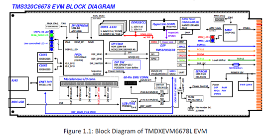
    [EMAC port 1 = SGMII_0 = switch port 1 = AMC backplane lines] .Note it is not available without the AMC chasis.
    [EMAC port 2 = SGMII_1 = switch port 2 = RJ45 connector]

    Regards, Eric

  • Hi lding  ,
    Thanks very much for help me,
    I have another question ,
    When i run the example (which test the platform ) in this directory :
    E:\ti\pdk_C6670_1_0_0_17\packages\ti\platform\evmc6670l\platform_test
     It gives in the console window that :
    [C66xx_0] EMAC port 1 connected to the PHY. 
    [C66xx_0] MAC Address = 40:5f:c2:bb:a8:31 

    Q1.  what it mean by that  EMAC port 1 connected to the PHY ,Does this mean that EMAC port 1 = SGMII_0 = switch port 1 is RJ45 connector ?
    if yes : 
    Q2. Does this mean that the MAC address which is printed in the LAN Card (which is connected to the RJ45) is   40:5f:c2:bb:a8:31 ?
    Q3. Does this mean i must reconfigure the mac address of EMAC port 1 in the demo example ?


    Thanks in advanced ,
    Muhammad . 

  • Q1, Different documents may count EMAC starting from 0 or from 1. Look the attached 6678 EVM diagram (should be same for 6670). The first EMAC port is connected to AMC connector, the second EMAC is connected to RJ45.

    Q2. The printed MAC is the MAC address of itself (DSP).

    Q3. Yes.

    Regards, Eric 

  • Hi lding ,
    Thanks very much for your efforts with me , Excuse me i am a beginner user with Texas instrument so  i asked a lot of questions ,
    After your answer it seems that i must reconfigure:
     
    1- The source and the destination MAC address of the pktMatch array which is implemented at  cppi_qmss_mgmt.c file  which transmitted from Board_1(TX)  with the following configuration :
    Source MAC address will be : The MAC address which i get it from running platform_test example in Board_1
    Destination MAC address :The MAC address which i get it from running platform_test example in Board_2 (RX)
    and the same with the IP and the port number .

    2-a)  Board_1: At the Init_Cpsw i will reconfigure the macAddress2 with the The MAC address which i get it from running platform_test example in Board_1
    b)The same thing withe Board_2 (Rx)

    3)update the Add_MACAddress (pa_mgmt.c) function in Board_1 : 
     reconfigure the Dest MAC in the ethInfo  with the MAC address of Board_2 (RX) and the same thing with the IP


    4)stop Loop back

    5)connected the two board through Ethernet cable which is connected in RJ45 of each board

     does this steps correct ??
    and how i configure the IP address for each board ??

    Thanks in advanced ,
    Muhammad . 

  • In packages\ti\drv\pa\example\simpleExample\paExample\pkttxrx.c, there is a pktMatch something like below, this is the packet sent out. You can find which offset is dest/source IP, UDP ports. In real usage, your application fill in a packet and call the sendPacket (unsigned char *gPkt, unsigned int length) to send it out. Please verify you can really send out packet before moving to how to receive (using a wireshark).

    unsigned

    char pktMatch[66] = {

    0x5c, 0x26, 0x0a, 0x3e, 0x46, 0x60,

    /* Dest MAC */

    0x90, 0xD7, 0xEB, 0x0D, 0x12, 0x56,

    /* Src MAC */

    0x08, 0x00,

    /* Ethertype = IPv4 */

    0x45, 0x00, 0x00, 0x34,

    /* IP version, services, total length */

    0x00, 0x00, 0x00, 0x00,

    /* IP ID, flags, fragment offset */

    0xff, 0x11, 0xa2, 0xff,

    /* IP ttl, protocol (UDP), header checksum */

    0x9e, 0xda, 0x6d, 0x58,

    /* Source IP address */

    0x9e, 0xda, 0x6d, 0xac,

    /* Destination IP address */

    0x70, 0x00, 0x70, 0x00,

    /* UDP source port, dest port */

    0x00, 0x20, 0x00, 0x00,

    /* UDP len, UDP checksum */

    0x32, 0x33, 0x34, 0x35, 0x36, 0x37, 0x38, 0x39,

    /* 80 bytes of payload data */

    0x3a, 0x3b, 0x3c, 0x3d, 0x3e, 0x3f, 0x40, 0x41,

    0x42, 0x43, 0x44, 0x45, 0x46, 0x47, 0x48, 0x49};