This thread has been locked.

If you have a related question, please click the "Ask a related question" button in the top right corner. The newly created question will be automatically linked to this question.

PCIe example - CSL_BootCfgGetPCIEPLLLock does not lock

Other Parts Discussed in Thread: TMDSEVM6657

hi,

I found out that PCIE_exampleProject just works fine (successful communication between EP and RC), when I boot the DSP via I2C POST boot in advance.

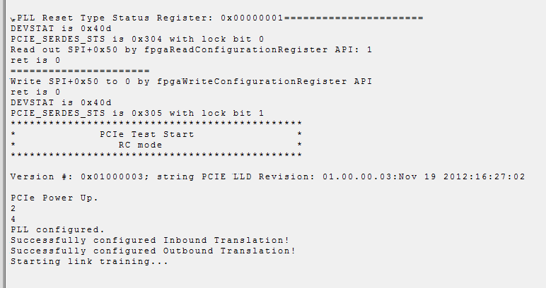
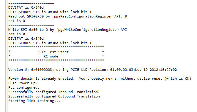
When I choose "no boot" or "ROM SPI boot" and load the PCIE_exampleProject.out afterwards the code will never leave 
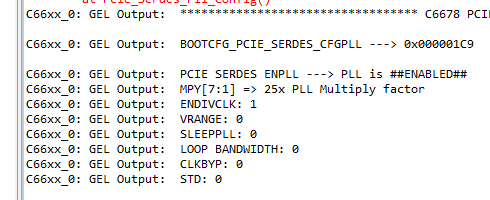
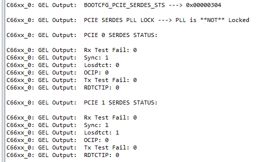
while (!lock)
{
CSL_BootCfgGetPCIEPLLLock(&lock);
}

. Even when I load the post_evmc6657l projects before to execute the booting process by hand I will have the same problem.

Any idea what part is missing to run the PCIE_exampleProject without booting in POST mode?

Regards, Gregor

  • I have to correct my last post: in "no boot" the PCIe PLL is looked after booting. That means I can perform the PCIE_exampleProject successfully. But for some reason when booting in SPI Mode the PCIe PLL will not lock. 

    I checked the PCIE_SERDES_STS register (0x0262015C) and bit 0 (LOCK) is never =1 when choosing SPI. But for no boot/POST it is =1.

    How can I force the der DSP during SPI boot to lock the PCIe PLL? Why is PCIe PLL locked when booting in "no boot" mode?

    Gregor

  • The PCIE example is tested in "no boot" mode, it works as you already verified. Why you need SPI boot mode to test PCIE? In "no boot" mode, there is the code in test application to configure the PLL (function pcieSerdesCfg()), so PLL is locked.

    Regards, Eric

  • hi Eric,

    thanks for this advice. I will check the function you mentioned.

    My plan is to boot the PCIE_example via SPI from NOR Flash to establish the PCIE interface and directly initiate the PCIE communication with my second EVM (is already waiting as PCIE EP that the first DSP comes up).

    Later on I will load the real data content via PCIE. To boot via PCIE is not convenient for me as the DSP has to be in EP mode for PCIE boot mode.

    Regards, Gregor

  • hi Eric,

    I am still have this issue.

    By the way: I am using the Boot Switches for SPI regarding to http://processors.wiki.ti.com/index.php/TMDSEVM6657L_EVM_Hardware_Setup#Boot_Mode_Dip_Switch_Settings on my TMDSEVM6657LS.

    The function pcieSerdesCfg() is already part of the PCIE_example and is executed successfully. As far as I understand this function enables the PCIE PLL.

    This is going well, as my boot.gel reports me:

    This PLL now is enabled, but in the next step it does not lock:

    Could it be a problem with some "main PLL/reference clock". I found this post: http://e2e.ti.com/support/dsp/c6000_multi-core_dsps/f/639/p/307521/1075609.aspx, but I cannot map their solution on my problem. 

    I checked different bootmode switch settings (see SPRS814A, 2.5.3), but just with "000" I could complete the boot process. Other switch settings will stuck during boot and PCIE PLL is not locked as well.

    When checking MAINPLLCTL0 I found kind of surprising setting:

    Regarding to SPRS814A, 2.5.3 I expect PLLM=39 and not =0.

    But "no boot" bootmode as the same values for MAINPLLCTL0  and is able to lock the PCIE PLL.

    Any idea what is missing during SPI boot to lock the PCIE PLL?

    Thanks and Regards, Gregor

  • Gregor,

    So you have:

    PCIE RC: code flashed to NOR and boot from SPI

    PCIE EP: code loaded by CCS and boot mode is "no boot"

    Is this correct usage and do you know if the SPI boot works correctly? For the PCIE clock, both EVMs use the local 100MHz clock genearted by oscilator. As you verified that PCIE SERDES can lock when both cards in "no boot" mode, so the PCIE test example is fine. We will check the main PLL setting.

    Regards, Eric

  • hi Eric,

    system setup is correct. The PCIE_example would also work if I boot in POST mode in advance.

    I see in BOOTCFG_BOOTCOMPLETE that for C6657 core 0 the Boot process is completed. Furthermore I changed the PCIE_example that I can see the console print outs in parallel in my Terminal (as during boot I cannot connect with debugger so I do not see what is going on). But in Terminal I see that the PCIE_examples runs fine until: "PCIe Power Up.\n". This is the last statement I see as the code afterwards stucks in the while()-loop waiting for the PCIE PLL. 

    The PCI_example itself: I just have one project and source. I use it as boot file and also as .out file which I load via CSS. And in that case its going fine. Maybe during processing .out > .bin for SPI-boot something is mixed up, but how should I find out?

    I am not sure if the PCIE_example can lock the PCIE PLL. After booting (no boot/POST) the PCIE PLL is already locked. Maybe the example does not do anything. Actually the problem is not necessarily related to the PCIE_example. We just know: no bot/POST: PCIE PLL locked. SPI boot (i also tried a simple hello world-example without any initialization: PCIE PLL not locked).

    How is the digital lock detector working? Maybe this module has a problem?

    Where can I see which clock is used for PCIE?

    Is the any silicon errata PLL thing with the C6657?

    Thanks, Regards, Gregor

  • Gregor,

    Thanks for debug this, I saw the same:

    In no-boot mode, just power on EVM without load any code, the PCIE_SERDES_CFGPLL (@0x2620358) is 0x1c9 and PCIE_SERDES_STS (@0x262015c) bit 0 is 1, indicating PCIE PLL is locked.

    In SPI NOR mode, just power on EVM without load any code, the PCIE_SERDES_CFGPLL (@0x2620358) is 0x1c9 and PCIE_SERDES_STS (@0x262015c) bit 0 is 0, indicating PCIE PLL is not-locked. This prevented further PCIE link-up.

    I am checking with HW people how this PLL is locked.

    Regards, Eric 


  • hi Eric,

    good that you could reproduce the problem.

    Maybe there is just some initialization or reset of PLL missing. Possibly the PCIe PLL tries to lock too early, when the main PLL is not stable.

    Regards, Gregor

  • hi Eric,

    any new idea related to that topic?

    Regards, Gregor

  • Gregor,

    Sorry, we are still debugging this.

    Regards, Eric


  • ok.

    That means you see a technical issue from TI side or did I miss to set something?

    Just let me know, if I can help.

    Thanks! + Regards, Gregor

  • Gregor,

    Thanks! This is an issue at our side.

    Regards, Eric

  • hi Eric,

    ok. good to know.

    With your experience of such issues: do you think you will find some work-around/bugfix or is it also quite probable that there will be no solution and PCIe will not be possible after booting via SPI? In the last case, we have to consider a re-design of our board and would need to know as soon as possible.

    How long do this kind of solution findings normally take?

    Thanks+Regards,

    Gregor

  • I opened a bug report for this. Then, some engineers will look into it. As the issue is for MCSDK 2.x release for C66x chips, this MCSDK is in maintainence mode and the latest release was Feb 2013, I don't have a planned date for the next release. Sorry for this!

    Regards, Eric


  • hi Eric,

    thanks for update! Please let me know about further information and time estimations about fixes by your engineers. Maybe it is just a small issue and we can find some work-around, because I am wondering why nobody else discovered this problem. That is why I think it might be just a small thing and other guys found a solution by them self.

    In case there is no solution or to find a solution would take very long, we have to consider alternatives.

    Actually in future I jut want to have a communication between my C6657 and a FPGA via PCIe. But as I want to have the FPGA as EP, the DSP has to be RC. I already found out that booting the DSP via PCIe means setting it as EP. So no solution for me.

    EMIF, Serial Rapid IO, Ethernet, Hyperlink is not available on our board for DSP. 

    I²C might be possible, but is not our favorite, because of low speed and the small EEPROM on the EVM. Even the simple PCIe-LinkTraining program is bigger than 128KB.

    Thanks+Regards,

    Gregor

  • Gregor,

    Can you confirm the current test for PCIE RC is on C6657 EVM? Is this a production EVM or pre-production EVM? For the SPI boot mode, what is the switch pin setting? The information on: http://processors.wiki.ti.com/index.php/TMDSEVM6657L_EVM_Hardware_Setup may have a problem. Can you try to set SW5, pin 2 to "OFF" as well. So, you should see DEVSTAT @ 0x0262_0020 = 0x0000_060D instead of 0x0000_040D. Do you see in this case PCIE PLL lock or not @0x0262_015C, BIT 0?

    Regards, Eric  

  • hi Eric,

    I get following:

    SW5, pin 2 "ON": 0x0262_0020 = 0000_840D and 0x0262_015C = 00000200

    SW5, pin 2 "OFF": 0x0262_0020 = 0000_860D and 0x0262_015C = 00000200.

    I used pin setting:

    ROM SPI Boot8 (off, on, off, off, on, on, on, on) (on, on, off, on, on, on, on, on)

    As I understood, the 8 means that it is booted as PCIe RC. But I guess it does not matter, as we do not use PCIe boot mode.

    Test is on TMDSEVM6657, Prod 1237-145.

    Regards, Thanks, Gregor

  • On the back of the EVM, what is the PCB REV and PCA REV?

    For the SPI boot mode, can you try to set SW5, PIN 8 to "ON", so 0x262_0020 = 0x0000_60D, is PLL lock?

    Regards, Eric

  • hi Eric,

    SW5, pin 8 is already "ON" (see screen shot above). I turned it to "OFF", but still "0000_860D".

    PCB REV: 18-00132-02

    PCA REV: 17-00132-02

    Regards, Gregor

  • I didn't find your screenshoot. "ON" is logical "0", "OFF" is logical "1", attached picture for my setup to get "60D". My EVM is an older revision, I will try to find a new one with your revision.

    Regards, Eric


  • hi Eric,

    I confirm that I have the same switch settings and get "0000860D" as DEVSTAT.

    Do you have any idea, why my PCIESSMODE is set to RC (10)? I changed the setting of SW5, pin7&8, but could not see any influence on that.

    Gregor

  • Gregor,

    I don't know why your EVM switch pin setting can't be reflected in the DEVSTAT register. Did you try to update FPGA image yourself? I guess not. I tried the above pin setting on a production card (same PCB REV and PCA REV as yours), and my DEVSTAT shows the 0x0000_060D. You can try an additional 6657 EVM if you have. I believe you need to contact the manufacturer for the issue why switch pin setting not showing on DEVSTAT.

    For the PCIE PLL is not locked, this may be a FPGA issue which is not working correctly under SPI boot mode, we are debugging this.

    Regards, Eric

  • Gregor,

    - In SPI boot mode, DSP is expecting a PCIE reference clock externally (from AMC edge) instead of internally (from on-board oscilator), that is why PCIE PLL is not locked.

    - In no-boot mode, the DSP is expecting the PCIE reference clock internally, so you have PLL lock.

    - The clock selection is controlled by the FPGA code.

    I don't know how the PCIE reference clock used in your system. Is the FPGA (PCIE EP) use a local narrow band on-board clock? Or it uses a spread spectrum clock?

    If your FPGA use the former, for 6657  (PCIE RC) side, you can have software in your application code (which boot from SPI/NOR) to overwrite what FPGA selected to bypass this problem.

    You can refer to the code example in: ti\mcsdk_2_01_02_06\tools\boot_loader\ibl\src\device\c66x\c66xinit.c, below snippet we used to select external clock by setting SPI base + 0x50 to 1. You need to set this to "0" instead in your case.

               /* Write ICS 557 Clock Selection Control Register in the FPGA */
                /* 1 : FPGA_ICS557_SEL s driven high */
             DEVICE_REG32_W(DEVICE_SPI_BASE(0) + SPI_REG_SPIDAT0,
                               FPGA_WRITE_REG_CMD(FPGA_ICS557_SEL_CTRL_REG,1));
                chipDelay32(10000);
                /* Reset SPI */
                DEVICE_REG32_W (DEVICE_SPI_BASE(0) + SPI_REG_SPIGCR0, SPI_REG_VAL_SPIGCR0_RESET);

    The explanation of this bit is in 6657 EVM technical Reference Manual:

    Please let me know if this works for you or not.

    Regards, Eric

  • hi Eric,

    thanks a lot for debugging.

    I did not change the FPGA code. I have 2 TMDSEVM6657LS, connected via CI2EVMBOC: EVM_A with programmed NOR Flash (this is the EVM we were talking about so far) and EVM_B (NOR Flash was never programmed by me).

    First I checked my BOOTCFG_DEVSTAT Register again:

    EVM_A: 

    0x0000860D for SPI-Bootmode + SW5, PIN2 = OFF (like your picture)

    0x0000840D for SPI-Bootmode + SW5, PIN2 = ON

    EVM_B: 

    0x0000060D for SPI-Bootmode + SW5, PIN2 = OFF (like your picture)

    0x0000040D for SPI-Bootmode + SW5, PIN2 = ON

    I was pretty happy to see the expected values for EVM_B, so I programmed the NOR Flash with my PCIe-Boot example. After booting I checked BOOTCFG_DEVSTAT for EVM_B again and unfortunately I saw the same values like EVM A (0x0000860D  and 0x0000840D).

    But for some (unknown) reason EVM_B is booting further. I see "Starting link training" in my HTerm what suggests that the PCIe PLL is locked. (I never had this with EVM_A). But when I check PCIE SERDES PLL LOCK I see that "PLL is **NOT** Locked".

    When I power up EVM_A (in no boot) and run the PCIe example (via Debugger) in EP mode, I just see that both sides have started their link training, but no successful connection.

    So far PCIe example was just successful when I started EVM_A and EVM_B in "no boot"-Mode and start PCIe example via Debugger on both EVMs.

    If I understand you explanation about the PCIe clock correctly, I have to force my SPI-boot-EVM (EVM_B, RC mode) to use the local on-board oscilator? 

    I tried this:

    // SPI workaround
    /* Write ICS 557 Clock Selection Control Register in the FPGA */
    /* 0 : FPGA_ICS557_SEL s driven low */
    DEVICE_REG32_W(DEVICE_SPI_BASE(0) + SPI_REG_SPIDAT0,FPGA_WRITE_REG_CMD(FPGA_ICS557_SEL_CTRL_REG,0));
    chipDelay32(10000);
    /* Reset SPI */
    DEVICE_REG32_W (DEVICE_SPI_BASE(0) + SPI_REG_SPIGCR0, SPI_REG_VAL_SPIGCR0_RESET);

    I checked:

    Did I understand it right?

    Unfortunately its not working. PCIe PLL is not locked and both sides remain in link training, but do not go further.

    Thanks+Regards,

    Gregor

  • Gregor,

    Sorry for the delay, the issue to resolve is PCIE PLL lock. If It is not lock, the PCIE link can't up. I verified a different code in SPI boot mode and it worked:

    unsigned char value = 0, ret = 1;

    printf("======================\n");

    printf("DEVSTAT is 0x%x\n", DEVICE_REG32_R(0x2620020));

    printf("PCIE_SERDES_STS is 0x%x with lock bit %d \n", DEVICE_REG32_R(0x262015C), DEVICE_REG32_R(0x262015C)&0x1);

    printf("Read out SPI+0x50 by fpgaReadConfigurationRegister API: ");

    ret = fpgaReadConfigurationRegister(0x50, &value);

    printf("%d\n", value);

    printf("ret is %d\n", ret);

    printf("======================\n");

    printf("Write SPI+0x50 to 0 by fpgaWriteConfigurationRegister API");

    ret = fpgaWriteConfigurationRegister(0x50, 0);

    printf("ret is %d\n", ret);

    printf("DEVSTAT is 0x%x\n", DEVICE_REG32_R(0x2620020));

    printf("PCIE_SERDES_STS is 0x%x with lock bit %d \n", DEVICE_REG32_R(0x262015C), DEVICE_REG32_R(0x262015C)&0x1);

    ==================================

    The printf is for debug purpose, the DEVSTAT should be 0x0000_040D all the times, with the setting of switches in SPI boot mode http://processors.wiki.ti.com/index.php/TMDSEVM6657L_EVM_Hardware_Setup

    "ret" should be "0" for success FPGA read/write operation. You should see read 0x50 return "1" at the first time, indicating PCIE expects a reference clock EXTERNALLY. After you calling the write API, with 0x50 to 0, you should see PCIE PLL lock (and read 0x50 returns 0).

    The read and write API code you can refer to   ti\pdk_C6657_1_1_2_6\packages\ti\platform\evmc6657l\platform_lib\src\evmc665x_fpga.c.

    One thing to note is for FPGA_MAX_ADDR_OFFSET, it is defined as 0x3F somehow, this preventing you operating at address 0x50. I changed it to 0x5F. Then the above APIs can read/write 0x50 address properly and when 0x50 is set to "0", I have PCIE PLL lock.

    Please let me know if this works for you or not. First, if PCIE PLL can lock in SPI boot mode, then can you have PCIE link up?

    Regards, Eric

  • hi Eric,

    thank you for providing that code example.

    I set the switches in SPI boot mode as recommended and increased FPGA_MAX_ADDR_OFFSET to 0x5F and I get a PCIe PLL lock as you just described in your last post. This my protocol via UART during booting:

    One questions: When I run this code example via dubugger after booting the DSP via SPI (protocol of that is just above), I will get DEVSTAT = 0x840d and PCIE_SERDES_STS = 0x30d instead of the values in the picutre above.

    Are these two changes something you would expect? Is PCIE_SERDES_STS = 0x305 (during boot) ok?

    For your first question: Yes, now PCIe PLL can lock.

    For your second question: I cannot test now, as I destroyed the CLK_MUX (U1) on one EVM by causing a shortcut during checking with my scope. So now the CLK_MUX never provides some usable PCIE reference clock in all boot modes. I ordered a new module by IDT. When I can repair the board, I will let you know about the second question.

    Thanks, Regards, Gregor

  • Gregor,

    0x840D vs 0x40D, the extra setting bit means PCIESSMODE as PCIE RC, this is latched to SW5 PIN 7 AND 8 of 6657 EVM, I don't know how they are set. I assume you have the code flashed to SPI NOR and put DSP in SPI boot mode to run, after running the code, why you need to use CCS debugger to load and run the same code? Just a trial? 

    For 0x305 for the PCIE_STS register, this should be fine.

    Regards, Eric

  • hi Eric,

    good news: I think I could repair the EVM (replace part B22 on EVM) and can keep on testing.

    I see in "no boot" that both EVM can lock their PCIe_PLL and with your workaround I also can force them during/after SPI boot to choose the internal ref_clk and lock PCIe_PLL again.

    Unfortunately I cannot finish the PCIE_example successfully.

    My setup:

    Board A: booting via SPI the PCIE_example (incl. workaround), load PCIE_example via debugger and set to RC.

    Board B: no boot, load PCIE_example via debugger and set to EP.

    -> run both boards.

    Both DSP will never leave this section in pcie_sample.c: (for RC and EP respectively)

    Obviously that dstBuf.but never become full. That means, I see "Link is up", but nothing beyond.

    I just tried to boot Board A and B in "SPI" and checked the PCIE_SERDES_STS.

    I noticed, that PCIe_PLL is locked on both EVM, but register itself does not contain the same value.

    The board I had to repair is: PCIE_SERDES_STS = 0x30D, the other one: PCIE_SERDES_STS = 0x301.

    So the further one has a Lostdct and Sync for PCI0, the later one none of them.

    Could this cause my problem?

    Thanks+Regards,

    Gregor

  • Gregor,

    The PCIE_SEREDS_STS doesn't look right when PLL is locked (but I want you to check this before PCIE test starts: one side is SPI boot, the other is no boot, for example, after PCIE link up, what is the PCIE_SEREDS_STS?, then wait for a few seconds, can you check again, if PCIE link still up and PCIE_SERDES_STS still ahs error)?

    When the PCIE code stuck, I am not sure it is because that SERDES status is not right (but you already pass the checking code and link up) or the PCIE SW has the problem. Let's rule out the PCIE SW first, this need you use CCS JTAG to check many memory locations:

    - is the link up and stable @0x21801728 at both sides?

    - the RC writes a pattern to EP, did you see it at RC's memory 0x6000_0000?

    I uploaded a document I tested with both sides with no-boot mode for your comparsion. Perhaps you can upload the same for me to check.

    Then, do you know the PCIE test works or not with no-boot mode on both sides, after one card repaired? I don't understand if PCIE link is up and stable why they can't exchange data.

    Regards, Eric

    5226.PCIE_translation_Ver2.docx

  • hi Eric,

    thanks a lot for your comprehensive information.

    1) My configuration is: Board A boots via SPI the PCIe_example in RC mode (incl. your workaround). Board B is in no boot - already up, loaded the PCIe_example and waiting as EP for Board A to show up.

    2) Yes, I have the tested the PCIe_example after repair for both boards in no boot mode: it is working. But I also noticed that it is possible to get both boards (RC/EP does not matter) in the "Link is up"-state, even if the other board is still waiting at "main". 

    I discovered following rule: I run one board with PCIe_example alone -> stop at "Starting link training". I stop that board and restart, but not running = waiting at main. I run the other board: It will stop at "Link is up.". If I restart, rerun that board again, it will hold already at "Starting link training."

    So I guess that the board will see some previous state of the other board and we cannot trust always in "Link is up".

    3) As references I read the register for "no boot - no boot". Same as your values.

    I did the same for "SPI - no boot" and I discovered some memory reading problems in the EVM I had to repair before. So I changed the roles (board A = repaired EVM, now in no boot, board B in SPI). I did that before with no success, but now: it was working - same results as no boot.

    I have no idea what changed compared to my last test. The link establishment is not always successful, even in no boot - no boot. maybe, I just was unlucky last time.

    Thanks + Regards.

    Gregor

  • now I know why it was not working so far:

    It is just successful the first time, when I PRO/reboot both sides before. If I try it again, both side stuck at "Link is up" but do not go further. Probably there is some bit set which prevents the PCIe_example to do the next step.

    This is probably the same issue as described in 2) above.

    I will sent you the word-doc in the problematic case later on.

    Gregor 

  • Gregor,

    - Please push both EVM cards AMC edge securely into the break out card, if it is loose you will not get link up no matter what boot modes are.

    - In the PCIE test example, the PCIE module is turn on by pciePowerCfg(). I always power cycle both cards for a new run, so I avoided "remember the old status". If this is not feasible for you, you can add a similar code inside main to power off PCIE first and then power it on.

    void main() {

    ....

    pciePowerOffCfg(); ====> write a function to turn PCIE off and call here

      /* Power up PCIe Module */
      if ((retVal = pciePowerCfg()) != pcie_RET_OK) {
        System_printf ("PCIe Power Up failed (%d)\n", (int)retVal);
        exit(1);
      }

    The code of power off should be just the reverse of what you did in Power it on, you may check PSC user guide for more details. http://www.ti.com/lit/ug/sprugv4b/sprugv4b.pdf. This can help you re-run the code without power cycle the cards.

    Regards, Eric

  • hi Eric,

    thanks a lot. That's the solution.

    With "PowerOffFunction" its working now in every run.

    Regards, Gregor