This thread has been locked.

If you have a related question, please click the "Ask a related question" button in the top right corner. The newly created question will be automatically linked to this question.

Very slow GPIO read on TMS320C6678

Other Parts Discussed in Thread: TMS320C6678, ADS1278

Hi All,

I am pretty new to TMS320C6678 programming.I know this subject was discussed multiple times but I am not sure I am able to solve this myself so her it goes.

At the moment I am trying to detemine the GPIO speed on TMS320C6678, TMDSEVM6678LE evaluation board. The code I am using is at the end of this post. Basically I flip one of the GPIO pins (through CSL_GPIO_setOutputData/CSL_GPIO_clearOutputData) and observe the output on the oscilloscope. I measure the length of the positive pulse on pin 15 for two cases: 

1)  the CSL_GPIO_setOutputData is immediately followed by CSL_GPIO_clearOutputData on GPIO pin 15

2) The CSL_GPIO_getInputData is inserted on other pin (say pin 5) between CSL_GPIO_setOutputData  and CSL_GPIO_clearOutputData 

For the first case, I am getting the pulse length of 100ns (50ns per single flip), and for the second case I am getting 1.2us (1200ns), which means the read actually takes 25 times more time than the write!!

I understand (or so it seems) that the read speed is defined by GPIO latching clock speed by manipulating some PLL registers. However I am not sure how to increase this speed (~250ns read would satisfy my needs). So here are my questions:

1. How to calculate and set the GPIO clock speed and is there a reference manual on the subject for this particular device?

2 Can this be done programmatically or this info should be in .cmd or .cfg or GEL file?

3. If this can be done programmatically, is there an API for this within MCSDK bundle and what particular module I should look for?

4. If it is possible, can somebody give a code snippet?

Any help on this subject would be greatly appreciated.

Best Regards,

Alex

P.S. here is the code I have been using for testing:

#include <ti/csl/csl_gpio.h>
#include <ti\csl\csl_gpioAux.h>

#include <ti/csl/csl_tmr.h>
#include <ti/csl/csl_tmrAux.h>
#include <ti/csl/src/intc/csl_intc.h>
#include <ti/csl/src/intc/csl_intcAux.h>

void main(void)
{
int i,j;
Uint8 dat;
CSL_GpioHandle ghGpio;
unsigned int DataArr[4];

/* Initialize GPIO module */
ghGpio = CSL_GPIO_open(0);
CSL_GPIO_setPinDirOutput (ghGpio, 15);

for (i=0;i<14;i++)
CSL_GPIO_setPinDirInput (ghGpio, i);


for (i=0;i<10000000;i++)
{

  CSL_GPIO_setOutputData (ghGpio, 15); // 50ns

  CSL_GPIO_getInputData(ghGpio,5,&dat); //1.2 us !!!

  CSL_GPIO_clearOutputData (ghGpio, 15); //50ns

  //some delay

  for(j=0;j<200;j++)
  {
    DataArr[j % 4]=0;
  }

}

}

  • Hi,

    For GPIO set and clear operation CSL function directly access the register field (SET_DATA and CLR_DATA) to set and clear the specific bit fields. In GPIO read operation CSL library function not directly read the GPIO  Input Data Register (IN_DATA), it use the local macro function. That only it takes more cycle for read operation.

    CSL_IDEF_INLINE void CSL_GPIO_setOutputData 
    (
        CSL_GpioHandle  hGpio,
        Uint8           pinNum
    )
    {
        Uint8       bankIndex, bitPos;
        
        bankIndex = pinNum / 32;
        bitPos = pinNum % 32;
    
        hGpio->BANK_REGISTERS[bankIndex].SET_DATA = 1 << bitPos;
        return;
    }
    
    CSL_IDEF_INLINE void CSL_GPIO_clearOutputData 
    (
        CSL_GpioHandle  hGpio,
        Uint8           pinNum
    )
    {
        Uint8       bankIndex, bitPos;
        
        bankIndex = pinNum / 32;
        bitPos = pinNum % 32;
            
        hGpio->BANK_REGISTERS[bankIndex].CLR_DATA = 1 << bitPos;
    
        return;
    }
    
    CSL_IDEF_INLINE void CSL_GPIO_getInputData 
    (
        CSL_GpioHandle  hGpio,
        Uint8           pinNum,
        Uint8           *inData
    )
    {
        Uint8       bankIndex, bitPos;
        
        bankIndex = pinNum / 32;
        bitPos = pinNum % 32;
            
        *inData = CSL_FEXTR (hGpio->BANK_REGISTERS[bankIndex].IN_DATA, bitPos, bitPos);
        return;
    }
    
    /* the Field EXTract (Raw) macro */
    #define CSL_FEXTR(reg, msb, lsb)                                            \
        (((reg) >> (lsb)) & ((1 << ((msb) - (lsb) + 1)) - 1))

    Better to directly access the Input Data Register (IN_DATA) on your test application and read the GPIO bit field, It will help to reduce the read time.

    Thanks,

  • Hi Ganapathi,

    Thank you very much for your reply.

    During my testing I also tried what you suggested like this:

    Uint32 bitfield;
    .
    .
    //CSL_GPIO_getInputData(ghGpio,5,&dat); //use macro: 1.2 us !!!
    bitfield=ghGpio->BANK_REGISTERS[0].IN_DATA; //access bitfield directly: 1.2 us !!!
    .
    .

    The result is exactly the same (1.2us) for multicore DSP running at 1 GHz.

    So is it possible to adjust the GPIO input latching clock frequency, something along the lines of this post: e2e.ti.com/.../295398 ?

    I found the PLLC library in CSL so I quess I can use it for that purpose?

    Best Regards,

    Alex
  • Hi Ganapathi,

    One more thing: according to GPIO timing diagram for TMS320C6678 (www.ti.com/.../tms320c6678.pdf , page 231) the read should be just ~3 times slower than write, i.e. ~150ns

    Best Regards,

    Alex
  • Here is an update on my previous post:

    According to TMS320C6678 (www.ti.com/.../tms320c6678.pdf , page 231) the write time is (36*C-8) and read time is (12*C), were C is 1/SYSCLK1=1ns for 1 GHz processor I have. So it seems the read should be actually >2x times faster than the write, which means I have even worse discrepancy like 60x times read slow down compared to specs while the write is spot on.

    To clarify further, I run the code given above through the CCS 5.2.1, Blackhawk mezzanine board, release build, the evaluation board switches are in "No Boot" mode.

    For a system we developing the speed of GPIO is of critical importance, so any insight on what is the source of the problem would be more than appreciated.

    Thank you,

    Alex
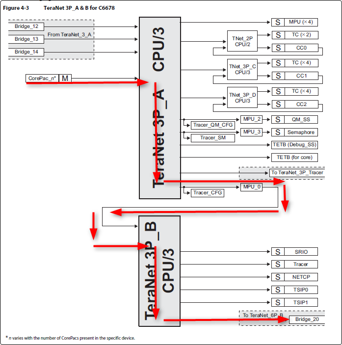
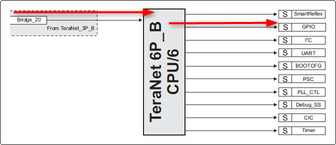
  • I think some clarification is needed regarding the data sheet specs.  These specs describe the GPIO peripheral and its associated I/O cell.  These do NOT comprehend system level considerations such as the impact of the interconnect.  The path from the CPU to the GPIO peripheral is found in the data manual.  Here's a quick mark-up:

    So as you can see, we are going through multiple bridges to get from the CorePac to the GPIO peripheral.  And there is sharing among other peripherals as well, e.g. if a different CorePac is trying to access UART or I2C on that same bridge, then there will be arbitration happening within the interconnect.  Finally, keep in mind that a read is fundamentally much different than a write.  Writes can be "fire and forget" where the CPU continues on while the write propagates to the peripheral.  A read requires the CPU to stall until the data comes back, and further more the path length effectively doubles since the data request has to go all the way to the peripheral, and then the data comes all the way back.

    So I think the results you're seeing are likely the expected results.  Now that said, there might be some optimizations to be made.

    Can you provide an overview of what you're trying to achieve?  Also, how are you doing the measurements?  Have you tried a test where you simply write a pattern such as low, high, low, high (with no reads in between)?

  • Hi Brad,

    Thank you very much for your response.

    What I am trying to achieve is the (condemned multiple times) bit banging to acquire the data from 10 multi-channel ADC's (ADS1278, 8 channels) at 10 KSPS per channel, by emulating the SPI protocol through GPIO. The reason for not using SPI directly is that this particular ADC allows daisy-chaining of no more than 20 channels in high precision mode because its SPI clock cannot be higher than the ADC modulation. frequency. There is another multi-channel ADC (ADS 1298) which does not have this SPI frequency limitation, but the ADS1278 has much higher quality internal decimation filter, and our main challenge is to effectively suppress strong parasite signals outside the pass band.

    How I did the measurements (the final timing is a little different from the code snippet in the original post):

    1) First, I simply wrote a pattern of low, high, low, high, no reads in between to pin 15 and measured the length of the positive pulse on the oscilloscope:
    CSL_GPIO_setOutputData (ghGpio, 15); // 50ns
    CSL_GPIO_clearOutputData (ghGpio, 15); //50ns

    2) Then, I inserted the following statement between high/low commands and measured the length of the positive pulse again :

    CSL_GPIO_setOutputData (ghGpio, 15); // 80ns
    bitfield=ghGpio->BANK_REGISTERS[0].IN_DATA; //1 microsecond !!!
    CSL_GPIO_clearOutputData (ghGpio, 15); //80ns

    The test was run under CCS 5.2.1, Blackhawk mezzanine board, release build, the evaluation board switches are in "No Boot" mode.

    Best Regards,

    Alex
  • Hi Brad,

    Forgot to mention: we don't plan to use neither UART nor I2C in our system, so if "locking" them somehow might help, it would be a viable solution.
  • Aleksandr Lisovich said:
    The reason for not using SPI directly is that this particular ADC allows daisy-chaining of no more than 20 channels in high precision mode because its SPI clock cannot be higher than the ADC modulation. frequency. There is another multi-channel ADC (ADS 1298) which does not have this SPI frequency limitation, but the ADS1278 has much higher quality internal decimation filter, and our main challenge is to effectively suppress strong parasite signals outside the pass band.

    Can you further elaborate?  So why don't you use the 6678 SPI (hardware) at a speed that is within spec of your data converter?  Or are you saying that you're already using the hardware SPI, but you're catching the "spillover" (due to the speed limitation) with a software SPI?

  • Hi Brad,

    I cannot use the 6678 hardware SPI because I have 10 ADCs, 80 channels total, and one can daisy-chain only "2.5" ADS1278 (20 channels max, this is the limitation of ADS1278 design) in high precision mode. Using GPIO would allow me to read the data from all 10 ADCs in parallel, thus overcoming the limitation.

    Best Regards,

    Alex
  • The "20 channels max" limitation comes from the fact that in ADS1278 the speed of read-out is tightly coupled with the modulation frequency, i.e. one cannot read data faster than Fmod.
  • Aleksandr Lisovich said:
    Using GPIO would allow me to read the data from all 10 ADCs in parallel, thus overcoming the limitation.

    What bit speed are you trying to achieve on your software SPI interface?  Were you planning on having one core bit-bang multiple of these interfaces or were you going to have all the 8 CPUs bit-banging their own SPI interfaces in parallel?

  • What I was planning to do is to use one core to bing bang multiple ADCs in parallel as following:

    1. One core serves the interrupt on data ready signal coming from one of the ADCs (all ADCs are synchronized on startup) to one of GPIO pins
    2. Same core generates Chip Select signal which goes to all 10 ADCs in parallel
    2. Same core generates single SCLK sequence (through the timer interrupt) at ADC read bit rate which goes to all 10 ADCs in parallel.
    3. 10 serial data outputs from 10 ADCs get read through 10 GPIO pins by the same core.

    Further data processing is done on the rest of the cores.

    I was also thinking about possibility to generate control SPI signals using the available hardware SPI and reading data from 10 GPIO pins in parallel at the interrupt from hardware SPI going to one of GPIO pins instead of using the timer interrupt.

    The speed (bit rate) to be achieved for 10 KSPS per channel is 10000*8*24=1920000 10-bit words per second.
    At the extreme I can go as low as 5 KSPS per channel which corresponds to ~950000 10-bit words per second.
  • Aleksandr Lisovich said:
    The speed (bit rate) to be achieved for 10 KSPS per channel is 10000*8*24=1920000 10-bit words per second.

    I'm not following your math.  The 10,000 clearly corresponds to 10 KSPS.  What does the 8 correspond to?  And presumably the 24 is the size of each sample?  I assume the 10-bit words is a consequence of having 10 ADCs.

    What you're describing sounds very much like a software implementation of the McASP peripheral found on many of our other devices.  From what you've told me so far, this does not sound like a feasible architecture.  I do not have any suggestions in terms of improving the "bit bang speeds".  The performance you're observing is the expected performance.  So that said, I do not think it is suitable to achieve your requirements.  Sorry for the bad news.

  • Hi Brad,


    8 corresponds to 8 channels within a single ADS1278 chip, and 24 corresponds to the ADC resolution (24 bits).

    Indeed, this is a bad news. I wish there was some data sheet listing the maximum GPIO read speed somewhere in the docs...We need to do a lot of signal processing, that's why we chose this chip.

    How about using the EMIF interface then? There is an article ( www.ti.com/.../sdma003.pdf ) which describes how to use the TI FIFO chips to interface high speed ADCs with DSP throughthe EMIF/DMA. Do you think this something worth a try?

    Best Regards,

    Alex
  • Have you looked into using the TSIP for this purpose? There are 8 rx-serializers on each TSIP, so you could use the two TSIPs for this purpose (e.g. 8+2 or 5+5). I would advise you to start a fresh thread looking into the use of TSIP with ADS1278. From a cursory scan of the TSIP documentation it looks like it's made to do exactly the sort of thing you doing. Though just for context, I have not ever used the TSIP before (i.e. I spend most of my time on Sitara devices which use McASP and McBSP which are similar but different). If you start a fresh thread you can likely get some advice from someone more deeply knowledgeable. You may want to put a link to the new thread here in case others in the future want to see the other discussion too.
  • Hi Brad,

    I will take a look at TSIP and will start a new thread if it will seem suitable.

    Thank you very much for your help and support!

    Best Regards,

    Alex