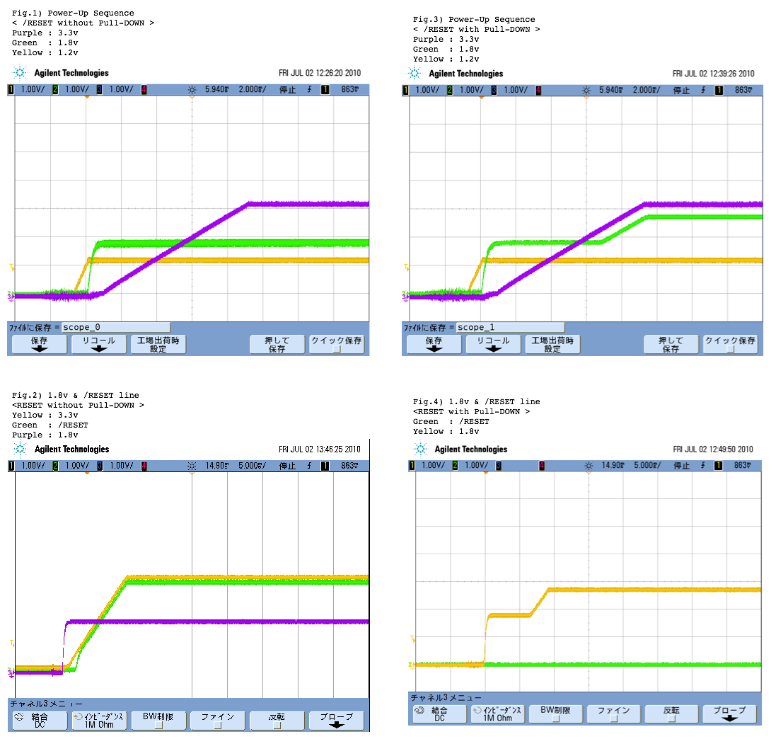
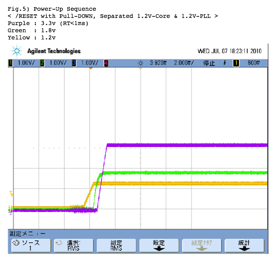
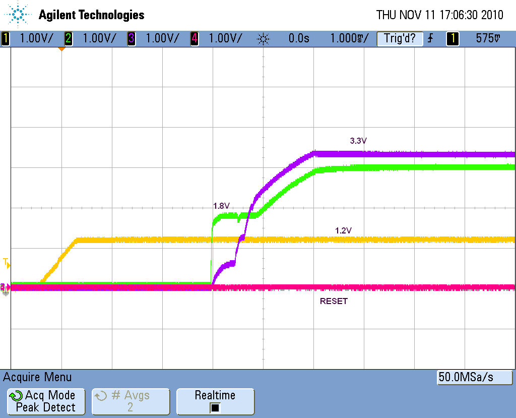
This thread has been locked.
If you have a related question, please click the "Ask a related question" button in the top right corner. The newly created question will be automatically linked to this question.
The /RESET pin belongs to power group B. So are you saying you have DVDD3318_B connected to 1.8V? When you say you are applying a "high" voltage to reset are you applying 1.8V or 3.3V? I don't see how it would be possible to apply 1.8V and somehow push DVDD3318_B up to 2.6V. On the other hand, if you are applying 3.3V to this pin then that is way out of spec and you are destroying the device.
Hi Kato
You need to ensure that the c6748 /RESET signal remains low during the entire power up sequence. There is a detection circuit that detects whether DVDD33_18_A/B/C supplies have 1.8V or 3.3V applied to them , this detection circuit will not work reliably unless it is ensured that during the entire power up sequence (1.2V supply --> 1.8V -->3.3V supply) the RESET signal is not low.
If there is a glitch on the reset signal or it is being pulled up high during the power on sequence 9or before completion) , we have seen this to push the DVDD 1.8V supplies to go to 2.4-2.7V.
Regards
Mukul
Hi Mukul and Brad,
Thank you very much for the quick response!
> this detection circuit will not work reliably unless it is ensured that during the entire power up sequence (1.2V supply --> 1.8V -->3.3V supply) the RESET signal is not low.
In our system, all DVDD3318_A/B/Cs are connected to 3.3v. Therefore, high for /RESET is also 3.3v LVTTL. And the order of power-up sequence on our C6748 board is designed to wake up 1.2v->1.8v->3.3v.
For my grounds in the previous post, I will attach a copy of screen from the measuring instrument.
Fig1) and Fig.2) show that, /RESET without PULL-DOWN, /RESET line goes up to 3.3v synchronizing with 3.3v and 1.8v stays correctly 1.8v.
Fig3) and Fig.4) show that, /RESET with PULL-DOWN, /RESET line is held low without any glitch and 1.8v goes up to 2.6v.
Hi Kato-san
Thanks for providing the snapshots of you reset and power sequencing. A few comments
1) In general I would still recommend that you have the device reset hooked through a reset supervisor circuit or use the resetout/pgood signal to tie to the c6748 /RESET rather then directly tying it to 3.3V
2) I can' t necessarily make out from the figures if the slew rate for the 3.3V has changed between Fig1 and Fig3 , can you confirm?
We have very recently heard of 1-2 more customers facing similar type of issue and we are still trying to root cause this better understanding the "commonality" between these designs to identify possible issues with the schematics.
We have seen that
1) Keeping the 3.3V ramp steep helps.
2) Putting a resistor ( 100 ohm - 1K ) between the 1.8V supply and ground also helps
In both of those cases , the 1.8V to 2.4-2.7V ramp up is not observed
At this point I don't want to say that just removing the pull down on the reset is the solution to your issue.
Would you be able to share your power management i/f to c6748 schematics with us? If you don' t want to do this on the public forums, do you have local TI support team that can assist forwarding the schematics to the factory team? Please advise.
Regards
Mukul
Hi Mukul-san
Thank you for the reply.
The slew rate for the 3.3V with/without the pull down on the reset is the same. Your suggestion make us doubt being something wrong on our circuit...
I will upload a part of our schematics which describe the power management and c6748 circuit.
Regards
Kato
Hi Kato-san
Thanks for sharing the schematics, I have not had a chance to review this in detail , however can you clarify , how is the DSP_RESET signal hooked up? It is not clear from the schematics, maybe it is on Pg 18 , which is not part of what you have shared in the PDF?
Still not sure why the RESET signal is closely "sychronized" with 3.3V supply in case there is a pull down on the signal but not without it. Although I think, the reset closely following the 3.3V is the reason for the issue you are observing. Why can't the DSP_RESET signal be hooked up to to the POK pin from U1 (EN5394 3.3V supply chip)? I wonder if that will fix the issue that you are observing?
Regards
Mukul
Hi Mukul-san
The DSP_RESET signal is connected to one of the FPGA-pin, which is our usual way.
It may be hard to recognize a fact which 1.2V pll line is isolated from 1.2V core line, R7 is Not Mounted in the sheet 2.
Now these 1.2V are combined by way of experiment, then 1.8V to 2.6V ramp-up is not observed regardless of RESET pull-down.
We don't know clearly the relation between the connection of 1.2V core/pll and the RESET pull-down, but we also imagine that if 1.2V core/pll is connected, a detection circuit will work good, if not, it will not. So our solution may be not to remove RESET pull-down, but also to connect both 1.2V lines. Is it likely as the root cause?
Regard,
Kato
Hi Kato-san
Yasuhisa Kato said:The DSP_RESET signal is connected to one of the FPGA-pin, which is our usual way.
Ok, I would like to assume that there is no issue with the /RESET signal and it goes high after the power up sequence, not track closely as shown in Figure 2 of your previously shared scope captures (that looks concerning and could cause issues in the power up sequence). Can you also confirm that for Figure 4, the RESET is not closely tracking the 3.3V rail, you only show 1.8V and /RESET in that capture.
Yasuhisa Kato said:We don't know clearly the relation between the connection of 1.2V core/pll and the RESET pull-down, but we also imagine that if 1.2V core/pll is connected, a detection circuit will work good, if not, it will not.
I am not aware of any relation to keeping 1.2V PLL supply isolated vs not isolated, impacting the IO supply detection circuit. However, I will discuss this with the design team to make sure I am not missing something.
I notice that the rise time for the 3.3V supply seems to be high. Can you confirm what it is? If it is in msec range, would it be possible to experiment changing the rise time (U1 , smaller Css value?) to see if it makes a difference. We have seen a shorter rise time of the 3.3V supply also "fix" the 2.6V ramp issue in 1 case ( root cause analysis are still work in progress).
Hope this helps.
Regards
Mukul
Hi Mukul-san
Mukul Bhatnagar said:Can you also confirm that for Figure 4, the RESET is not closely tracking the 3.3V rail, you only show 1.8V and /RESET in that capture.
Sorry for lacking of 3.3V rail in Figure 4, it is the same rail in other figures.
Mukul Bhatnagar said:I notice that the rise time for the 3.3V supply seems to be high. Can you confirm what it is? If it is in msec range, would it be possible to experiment changing the rise time (U1 , smaller Css value?) to see if it makes a difference. We have seen a shorter rise time of the 3.3V supply also "fix" the 2.6V ramp issue in 1 case ( root cause analysis are still work in progress).
Bingo! The rise time for the 3.3V line is more than 8ms. After changed to less than 1ms, 1.8V to 2.6V ramp-up is not observed even if the /RESET has the pull-down and 1.2V pll is isolated from 1.2V core. I will upload Figure 5 which shows no ramp-up problem.
As for two items - RESET pull-down and 1.2V-pll/-core lines, if you investigate further, if you find something and if it is not inconvenient for you, I would be very glad of your explanation. But I also think that it is not so easy to investigate those items and to get comprehensive understanding. Anyway, thank you very much for your support.
Best Regards,
Kato
One question, do you have any data as to the rise time of 3.3V supply? If that data ensure no ramp-up on 1.8V, we want to attach the pull-down to the /RESET...
Regards,
Kato
Hi Kato-san
Thanks for conducting additional experiments and confirming that sharper rise time is resolving the issue. I will update you if we have additional inputs on why a pull down on the reset or ganging the 1.2V supply helped.Those might just be giving some margin for this issue to show up or not, but we don't think that this should be the crux/root cause for the observed issue.
Yasuhisa Kato said:One question, do you have any data as to the rise time of 3.3V supply? If that data ensure no ramp-up on 1.8V, we want to attach the pull-down to the /RESET...
This is the part that is still under investigation, as this observation/issue has been reported recently. We will have additional updates on this in coming weeks. I apologize for any inconvinience that this might cause.
Regards
Mukul
Hi Mukul-san
Here's a few additional information for your investigation.
Regards
Kato
Hi Kato-san
Thanks for the additional updates.
Yasuhisa Kato said:Ganging the 1.2V supply was not an effective solution for this issue in some our boards.
This jives well with our understanding. We believe ganging the 1.2V supply was making your design marginally work likely due to some inter dependency on the 1.8V current draw etc. However this was expected to be a robust solution, and we do not plan to investigate this further.
Yasuhisa Kato said:This issue does not occur in the power sequence of 3.3V->1.8V->1.2V or 3.3V->1.2V->1.8V even if the rise time of 3.3V supply is more than 8ms.
Yes, this has been reported to work (bringing up 3.3V before 1.8V) . However this is in violation of the datasheet power up sequencing and is not an acceptable work around or solution to the issue.
We will continue to focus on providing better recommendations on 3.3V supply ramp time requirements and load on 1.8V supply etc, as a resolution to this issue. This is work in progress.
Regards
Mukul
Hi Mukul-san,
Mukul Bhatnagar said:We will continue to focus on providing better recommendations on 3.3V supply ramp time requirements and load on 1.8V supply etc, as a resolution to this issue. This is work in progress.
Is there any progress?
Hi Kato-san
This is still work in progress, and we hope to have a formal advisory available in coming months. If you need advanced information on this, please contact your local TI field support team.
In general , things that work to work around this issue is
1) Synchronous buck power management solutions that allows outputs to sink current , supplies that are capable of actively regulating the voltage up/down.
2) It has been reported that using a shunt regulator between the DVDD18 supply and VSS , to clamp the voltage below 2V also works well. We are conducting additional bench experiments to confirm on this (so far looking good)
3) A combination of bulk capacitance on the DVDD18 and slew rate on the DVDD1833_x supply. I believe this is what worked for your initial design assessments. We are finalizing the values for this, even though in general the #1 and #2 work around would seem more robust and acceptable, because bulk capacitance/slew rate combinations could possibly be susceptible to board changes etc (might need tweaking every time the cumulative capacitance value on the supply might change etc).
Hope this helps.
Normal 0 false false false MicrosoftInternetExplorer4
Hi Roger
The formal advisory to errata is still getting delayed due to some other higher priority items. Regret the inconvenience that this could be causing you and others dealing with this issue.
Do you have a local TI sales/field rep assisting you? If so, please provide the name and we can try to furnish the internal (release candidate) version of the advisory to you via them.
There is relevant information on this thread also, and if there is anything we can do help w.r.t to the issue you are seeing please post your queries here.
Regards
Mukul
Mukul,
My TI field apps engineer is Jason Brand in the UK. I asked him to chase this a couple of hours ago by email so any info you could give him would be helpful.
I tried the fixes suggested in this thread with no luck. If I put a 2.048V shunt reg on the 1.8V rail it just pulls the 3.3V rail down & when I remove it the 1.8V rail will go up to 3V. This is the first PCB of this job so I cannot be completely sure there is no other issue with the PCB. The processor is TMX320C6748. Of course it's also possible that the processor on this PCB is now damaged because the 1.8V limit has been exceeded, but I don't want to swap the processor just to end up with a pile of bad devices. I tried it on one other board with the same results. Attached a shot of the power rails on the processor. The 1.8V rail is used for DVDD18, the DVDD3310_A _B _C are connected to 3.3V.
Regards --- Roger
Roger
roger littlewood said:My TI field apps engineer is Jason Brand in the UK. I asked him to chase this a couple of hours ago by email so any info you could give him would be helpful.
Good to know you are in good hands. Have shared the internal advisory with Jason to forward to you.
roger littlewood said:I tried it on one other board with the same results. Attached a shot of the power rails on the processor. The 1.8V rail is used for DVDD18, the DVDD3310_A _B _C are connected to 3.3V.
If I remember correctly DVDD18 is the only 1.8V supply in your design as you don' t use DDR2/mDDR or the USBs and were using a set of discrete LDOs? So depending on the ramp time of your 3.3V supply and the load on your 1.8V supply , you could see the issue. I am assuming the load on your 1.8V supply is very minimal. Hopefully the workaround suggested can be applied to your existing design.
Regards
Mukul
Hi Mukul-san,
How about the workarounds to this issue?
My customer seems to be seeing same ploblem.
Thanks in advance for your cooperation.
Best regards,
j-breeze
Hi J-Breeze
The issue along with the suggested workarounds is now documented in the errata
http://www.ti.com/litv/pdf/sprz303c (Advisory 2.0.18, Pg 19)
Hope it helps. Let us know if you have any follow up question on this.
Regards
Mukul
Hi Mukul-san
Thank you for your information on the latest errata.
According to Figure 3 in the advisory, it is not required a potential delay b/w supply ramps during zone E, but my customer saw this problem under a condition.
The condition is that the delay is shorter than about 1ms.
Are there any requirements for the delay during zone E?
Regards,
j-breeze
There is no requirement for a delay during zone E. Once the 1.8V supplies are fully ramped then the 3.3V supplis mya be ramped. If you can provide more detail into the situation your customer is seeing we can take a look at it.
Regards,
Clay