This thread has been locked.

If you have a related question, please click the "Ask a related question" button in the top right corner. The newly created question will be automatically linked to this question.

My hot DSP wont power up! TMS320C6412AZDKA5

I have a DSP in my product that stops functioning when it reaches about 50*C. Within 0.1*C it stops and starts working. The failure comes when I have to power down the unit then power it up. If I let it run it works well past 60*C. All other circuits seem to come up same as before but the DSP wont even boot.


Below is some question that a tech asked me to answer then post it on here.


Here are some recommendations.

-       Check core and I/O voltage levels – Does it help if you increase voltage levels within the operating range

A)    I measured the voltage @ 1.21V would it really help to rais the voltage just 0.5V. it is hard to do because it goes to other devices

B)   In the design notes it talks about a A-500 device that is 1.4V core. Should the TMS320C6412AZDK5 cor be 1.4V instead of 1.2V.

-       Check clock (I believe you have already done this) . CLKIN should be running at the correct frequency.

A)   The clock frequency feeding CLKIN & AECLKIN was measured @29,999,860-29,999,200 over tempreture 26C to 59C

-       Make sure the clock and voltages have stabilized at proper operating conditions before de-asserting reset.

A)   The clock and voltages are stable for about 1.2 seconds before the reset\ pin rises.


Once you have done the above,

-       Are you able to connect to the DSP via JTAG ?

A)   When the DSP is too hot CCS cannot connect to the DSP through JTAG. Otherwise it can. (info: in order to connect to CCS another IC hast to send out a reset signal so CCS can connect. That chip is working fine and the reset signal is good @480uS long)

-       Are you able to read/write registers and internal memory using CCS – Maybe run a memory test at 50deg C

A)   Yes.

-       Are you able to read/write external memory, flash using CCS

A)   I only have Flash attached to the DSP I’m not sure that has to do with the JTAG but it is able to read it after it gets hot.

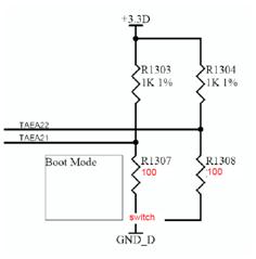
-       What stage in the boot process fails?

A)   The initial part it cannot boot at all.


Is there anything you can think of that would cause this problem? Anything that I need to check?


Jim

  • Does this happen on all your boards or just one, or a certain %?

    Usually when there is a failure like this it is some component outside the device that is failing leading to the DSP to fail, so what you are already looking at with the voltages and clocks is a step in the right direction. I can say the devices are tested to run up to 90C, and that they have an extremely low incidence of failure (i.e. a bad C6412), low enough that of the many customers I have worked with, I have never seen bad silicon (this goes for other TI processors as well).

    Since your voltages and clocks appear to be stable at this point, the next area I would check would be any of the logic devices surrounding the DSP, any buffers or muxes that could be failing and driving/not driving signals on the DSP that they should/should not be (since you see nothing maybe the reset line is getting messed up closer to the DSP). Outside of this, there is also the possibility of physical problems, if you are getting significant thermal warping of the PCB and losing connection somewhere.

    These are at least some ideas, a problem like this can be difficult to resolve, in general I would advise against jumping to the conclusion that the part itself is bad and examine everything around it very carefully.

  • Hi Bernie,

    I want you to now I think TI sells good DSP’s and use them as we need them. I am just pointing to where the problem seems to be.

    This problem happens on every board tested.

    There is very few components connected to the DSP. There is a Xilinx it uses the McASP and GPIO, a flash, and a MCu connected to /reset, I2C, and some GPIOs (we don’t use the GPIO’s here). Of course there is the ossilator, PLLV filter, JTAG port and an assortment of pull up and pull down resistors setting the mode.

    I want to thank you for your time. Which signals do you think I need to watch? I will continue examining the board.

    Jim

  • James Croker said:
    I want you to now I think TI sells good DSP’s and use them as we need them. I am just pointing to where the problem seems to be.

    I understand, I did not mean to sound like I was offended :), I just want to help guide you down the right path. The DSP is often the most obvious component to fail if something goes wrong with the PCB or surrounding discrete devices so we get this a lot.

    Since you mention the problem happens on every board tested, it is even more unlikely that multiple lots of devices would fail like this (if you are looking at only devices from the same lot than there is still a very small chance of some problem on the DSP end).

    James Croker said:
    Which signals do you think I need to watch?

    Since it never comes up, the first one that comes to mind is reset, though I imagine you have checked that many times already. Along these lines, do you get any particular error messages from CCS when you attempt to connect? Usually when the DSP is stuck in reset you get a fairly specific 'it seems your device is held in reset' error message.

    The others that would be of interest would be any of the boot mode or reserved pins, if these get mistreated you can get in odd test states that might make it appear the device is not booting. Though you already checked the input clocks to be clean, these are one of the most common points of thermal failure I have seen which would cause this like the reset, some oscillators get noisy over their operating temperature range.

    Sorry I don't have a silver bullet for this one, these situations tend to have too many variables.

  • 3527.DSP_SCH_with_heat_prob.pdf


    here is the Schametic, I wope it worked.

    as for the errors i get look below. i hav an idea i will change the boot mode resistors so they will only come up in JTAG mode and eliminate all other modes. i"ll poast what is the results when i ght them.

    To connect to the DSP I need to send a reset to the DSP then I can connect to CCS.

    This is the warning I usually get before I reset the DSP and try to connect.

    Error connecting to the target:

    Error 0x80002240/-116

    Fatal Error during: Initialization, OCS, Control,

    This error was generated by TI's USCIF driver.


    SC_ERR_CTL_TRASH <-116>

    A bad parameter value was detected within

    an internal data-structure of Unified-SCIF.

    The controller or Unified-SCIF may be in an invalid state.


    Sequence ID: 0

    Error Code: -116

    Error Class: 0x80002240


    Board Name: Encoder 6412 via SDXDS560R USB Emulator

    Cpu Name: cpu_0


    Abort:                   Close Code Composer Studio.

    Retry:                    Try to connect to the target again.

    Cancel:                 Remain disconnected from the target

    Diagnostic:         Run diagnostic utility.


    After its hot I get this warning first.


    Error connecting to the target:

    Error 0x80000262/-1154

    Fatal Error during: Memory, Execution, Initialization, OCS,

    The memory at 0x00000000 continually indicated it was 'not ready'

    The emulator was unable to regain control of the processor.

    The processor must be reset.


    Sequence ID: 0

    Error Code: -1154

    Error Class: 0x80000262


    Board Name: Encoder 6412 via SDXDS560R USB Emulator

    Cpu Name: cpu_0


    Abort:                   Close Code Composer Studio.

    Retry:                    Try to connect to the target again.

    Cancel:                 Remain disconnected from the target

    Diagnostic:         Run diagnostic utility.

     and then after I send a reset signal to the DSP I get this warning

    Error connecting to the target:

    Error 0x80002262/-116

    Fatal Error during: Memory, Execution, Initialization, OCS, Control,

    This error was generated by TI's USCIF driver.


    SC_ERR_CTL_TRASH <-116>

    A bad parameter value was detected within

    an internal data-structure of Unified-SCIF.

    The controller or Unified-SCIF may be in an invalid state.


    Sequence ID: 0

    Error Code: -116

    Error Class: 0x80002262


    Board Name: Encoder 6412 via SDXDS560R USB Emulator

    Cpu Name: cpu_0


    Abort:                   Close Code Composer Studio.

    Retry:                    Try to connect to the target again.

    Cancel:                 Remain disconnected from the target

    Diagnostic:         Run diagnostic utility.


  • James Croker said:
    here is the Schametic, I wope it worked.

    I see the schematic so it worked, the design looks very straight forward and nothing really sticks out as a problem at a schematic level, all the reserved and boot mode pins appear to be handled fine. One part that comes to mind here is the PLLV, it may be worth verifying that PLLV supply is stable and clean, as that can cause weird problems if it is out of spec.

    The emulation errors you have for before reset and after the reset with the over heated condition abuot a bad parameter in an internal data structure are fairly generic, just that something is wrong in the emulation logic.

    The error you get when you over heat about memory not being ready is also somewhat generic as there is not really a solution apart from resetting the device, but it means that the internal bus of the device is locked up. Essentially the emulator attempted to access some address (0x00000000 in this case) and the access never completed, so the emulator is waiting indefinitely for the memory to indicate 'ready'. Usually this would happen if you tried to access some invalid location in the memory map, but since it shows it at 0x00000000 which should always be internal SRAM, this makes it sound like the internal bus of the device is locked up, or otherwise in a bad state.

    Unfortunately neither of these really shed any light on what the real problem could be, other than that something is messing up the state of the processor.

    Since this involves temperature, I am curious how you are measuring the temperature of the device?

  • I have good news, when I set the DSP to “no boot” Mode I could always connect and run to CCS. There were hiccups, but if I reset CCS or tried again it worked. I went to 60C about 10C more than I see the problem.

    Bernie Thompson said:

    here is the Schametic, I wope it worked.

    Since this involves temperature, I am curious how you are measuring the temperature of the device?

    [/quote]

    The way I am measuring the device is with a Tenmars Thermometer I have one probe on taped to the top of the DSP and another on the edge of the case.

    Now I am trying to see what happens to the boot mode pins on start up. I will check the PLL voltage next

  • Bernie,


    Can you answer this question?

    In the design notes it talks about an A-500 device that is 1.4V core. Should the TMS320C6412AZDK5 core be 1.4V instead of 1.2V?

  • James Croker said:
    In the design notes it talks about an A-500 device that is 1.4V core. Should the TMS320C6412AZDK5 core be 1.4V instead of 1.2V?

    This is a good question, I wish the datasheet was more clear on this since the A can seem ambiguous when there is also an A representing silicon revision in the part number, I may have to file a bug against it. Based on the voltage mentioning in the silicon errata (page 5), I believe the A-500 they are referring to is the extended temperature device (this also makes more logical sense, higher core voltage will give more stability at the cost of power consumption and device life span), your part number is a commercial temperature range device and thus should not require the voltage boost, 1.2V core is right on for TMS320C6412AZDK5.

    If it was possible to adjust the core voltage, it would make for some interesting experimentation to see if the device works at a higher temperature if you push the core voltage spec, though I cannot technically recommend this since it would be outside of the datasheet specs we test the device with. If you were to push up the core voltage a bit and saw no change in the reaction of the device at higher temperatures than it would be a stronger indication of a problem outside the DSP itself.

  • All right, here is the summery of all tests I have done.

    1)      The system functions and fails to function when the temperature on the DSP changes between a few 0.1*C @ about 50C. The failure comes when I have to power down the unit then power it up. If I let it run it works well past 60*C. All other circuits seem to come up same as before but the DSP will not even boot and I cannot connect to CCS through JTAG even after I toggle the reset line.

    2)      If I set the DSP to “NO BOOT” mode, I can always connect to CCS.

    3)      The time from stable power supply and clock to the deserting of RESET signal is 1+ seconds. Voltages seem to track each other within a few mS.

    4)      Variations and stability of the 30MHZ system clock feeding CLKIN & AECLKIN was measured @29,999,860-29,999,200 over temperature range 26C to 59C.

    5)      Voltage @ the PLLV was 3.322V over temperature.

    6)      The two boot mode signals are stable until 600nS after the Reset rises. (except when it fails it doesn’t move)

    7)      All components, the flash, Xilinx, and AVR (MCU), are temperature appropriate.

    8)      The errors I get from CCS are generic indicating a RAM read error addr 0x0000000 so it is just stuck on an internal search. (See \\Fs1\eng_dept\IRAD\Active_Projects\ENG_181_AVC_Encoder_Develope\Testing\CURRENT\DSP_heat_problem\dsp_heat_report_error.docx for more details)

    9)      I have increased the voltage level from 1.2V to 1.2.85V. 1.3V is the most the other IC’s attached to the 1.2V can handle. This did not fix the problem but did alter the symptoms a little.

    a.       It seems that the temperature of the DSP seemed to fluctuate more from the failure to pass. It seems more like its not directally the temp of the DSP but the temperature of the board that matters. Iethor way I cant figure what is causing the lock-up on the DSP.

    10)   I checked the I2C and it moves about 600uS after the reset de-asserts when it works. Not at all when it fails.

    11)   I tried an experiment where I added two 100 ohm resistors to the boot mode pins to help change the boot mode from no boot mode to EMIF Boot Mode without cycling power. When it is cold, this system works well and I can see it in CCS, but when it gets hot I can see the no boot mode in CCS but when I give the DSP a reset signal it can no longer be accessed and doesn’t work. If I hit reset again in no boot mode, I can again connect it to CCS. (see figure)

    12)   I replaced R1303 and R1304 with stronger pill-up resistors to lessen any noise on the BOOT mode pins. No difference

    I do not know where to go from here any ideas would be appreciated.


    Jim Crocker


  • Hi Bernie,

    Here are the latest findings on the above problem. I had an old power supply board that was able to give the DSP core 1.4V. I plugged it in and I was able to get the DSP to boot up @ 70C wow. We cannot use it because we have a chip that requires a power-up sequence and this board does not have it. Therefore, I created a small LDO board and changed it a lot from 1.37V to 1.42V and nothing seemed to work. I delayed and speed up the 1.4V to 3.3V relationship, and still nothing.

    Therefore, I went back to the old PSU and changed the core voltage to 1.2V and it worked. The only difference was that the 3.3V had an over shoot at power on that went to 5V. I was able to ad a power supply to the old board and it failed at high temperature. Now here is the thing I was able to increase the working temperature by increasing the 3.3V, not that much but maybe 5C.  

    Have you ever heard of this? Any suggestions? 4452.good_power.TIF8228.new_w_ldo_bad.TIF

  • We need to know the maximum voltage level for the 3.3V supply on the TI DSP. 


    It appears that as the temperature increases the voltage requirement also needs to increases on the DSP during start-up is this common?  What is the maximum 3.3V that the TI DSP can handle for both low temp and high temp requirements (datasheet indicates that this device will operate to at least 90oC).  Our (GMS) goal is to be able to reach an operating temperature of 75 to 80oC at the device, when the chassis is at 70oC and be able to restart the system at temperature.   Currently our testing has shown that we are not able to restart the DSP when the temperature exceeds 59oC with an input voltage to the DSP of 3.44V (datasheet indicates the maximum 3.3 voltage can be as high as 3.46V).  The DSP Core voltage either at 1.4V or 1.2V has no effect on the start-up of the DSP at temperature.


    Summary question:

    Is temperature dependant on voltage of the DSP?

    What is the maximum voltage level for the 3.3V supply to the DSP?


  • James Croker said:
    What is the maximum voltage level for the 3.3V supply to the DSP?

    The max voltage for operation on the 3.3v rail is 3.46v as defined in the datasheet, pushing beyond this risks damage to the device.

    James Croker said:
    Is temperature dependant on voltage of the DSP?

    I am under the impression that this is typical (higher voltages improve stability to a point), however the device should not require voltages outside of the nominal datasheet voltages to operate throughout its temperature range, thus if you have to push the voltages higher to stabilize there is likely something else going wrong. What is actually going wrong in this case is harder to say, but raising voltages to compensate is just masking the underlying issue.

    The devices are tested over their operating temperature range and are known to work up to the 90C case temperature  for the commercial parts and 105C case temperature for the extended temperature variant. If you happen to have a EVM board for this device, it may be worth running it through the same thermal test to see if it responds in the same fashion, that could at least help to prove that the device itself can take it, though note that the EVM was not designed for extended temperature operation so I cannot guarantee how it will react.