This thread has been locked.

If you have a related question, please click the "Ask a related question" button in the top right corner. The newly created question will be automatically linked to this question.

TMS320C6748: 1.8 V power supply

Part Number: TMS320C6748
DSP_Power_Supply.pdfTMS320C6748EZWTA3 is used to perform the circuit design and check the operation.
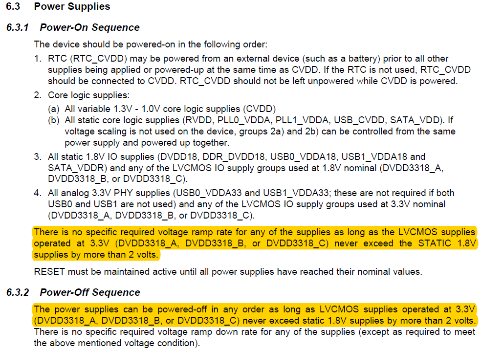
3.3 V is used as I / O power supply of DSP.
"problem"
When the voltage of the 1.8 V power supply for the DSP turns on the I / O power supply, the 1.8 V power supply part becomes 3 V.
I looked at the application note, but I can not solve the problem.
How do I take countermeasures?
I attach the circuit diagram of the power supply unit.
  • Hi,

    It sounds like 3.3V might be coming from either U7 or U8 to LDO_1V8 some how.

    Have you tried isolating U7 and U8 by removing JR6 and JR7 one by one?

    Check for shorts without power applied between LDO_1V8 and 3V3 as well as LDO_1V8 and VCC_IO while with all combinations of JR6 and JR7 populated/ removed.

    Can you list all of the destinations of the LDO_1V8 supply?

    Regards,
    Mark
  • Thank you for your reply.


    U8, JR7 are not mounted yet.

    All parts indicated by () are not mounted yet.

    Sorry at the lack of explanation.


    LDO_1 V8 I think that it is better to send all of the circuit diagrams of the relevant part than to write out the part to which the power supply is connected. I attach a circuit diagram.


    As a countermeasure against the problem that has occurred, we did the following things.

    With this, the phenomenon no longer occurs.

    May I think that the problem was completely solved with this measure?


    VCC_IO (3.3 V) Delete 5 capacitors 10 uF connected to power supply (C17, C18, C48, C69, C71 deleted)

    Connect 4 capacitors 10 uF to LDO_1 V8 (1.8 V) power supply

    schematic1R8V.pdf

  • Thank you for the schematics.

    I do not understand how you resolved the issue of 3.0V appearing on the 1.8V LDO_1V8 rail by removing bulk capacitors from the 3.3V VCC_IO rail, and adding bulk capacitors to the LDO_1V8 rail.

    Was the 3.0V observed after the supplies had settled down?

    Are you following the Power On sequence described i the datasheet section 6.3.1 Power-On Sequence?

    There is no specific required voltage ramp rate for any of the supplies as long as the LVCMOS supplies operated at 3.3V (DVDD3318_A, DVDD3318_B, or DVDD3318_C) never exceed the STATIC 1.8V supplies by more than 2 volts.

    I see you use 1.8V to enable 3.3V, so the 3.3V should never be more than 1.5V apart from the 1.8V rail (3.3V - 1.8V = 1.5V). Have you verified this?

    Regards,
    Mark

  • Thank you for your reply.

    >Was the 3.0V observed after the supplies had settled down?

    After supplying the 3.3 V power supply, I confirmed that the 1.8 V power supply does not become 3.0 V with the power supply stabilized.

    >Are you following the Power On sequence described i the datasheet section 6.3.1 Power-On Sequence?

    It follows the sequence written in the data sheet.

    >I see you use 1.8V to enable 3.3V, so the 3.3V should never be more than 1.5V apart from the 1.8V rail (3.3V - 1.8V = 1.5V). Have you verified this?

    Please tell me about this part in detail.

    Should we send the waveform of the power supply part?

  • Hi,

    I was referring to this statement in the datasheet.

    Regards,
    Mark