Tool/software: Linux
Hello,
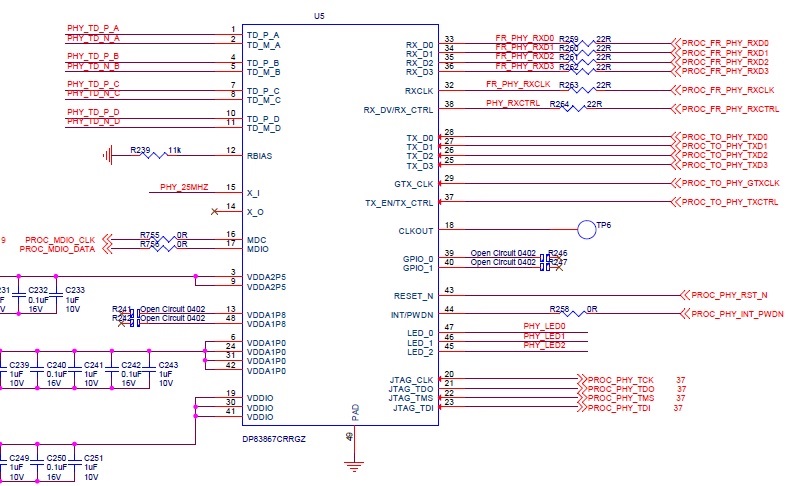
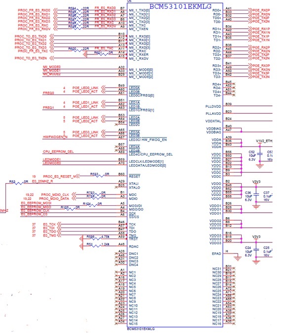
On my board I have connected MII_1 to BRCM switch and RGMII_2 is connected to TI PHY. I have already verified at u-boot level, at a given time either MII_1 with BRCM switch works OR RGMII_2 with TI phy is working – so there is no hardware or connection issue.
I am having hard time to make network working at Linux level. My requirement are as follows.
- RGMII_2 (TI-PHY) will connect to outside world to external router and gets IP address from external DHCP server/router. I would like this interface to be come up as "eth0".
- MII_1 – BRCM switch, I will be running DHCP server locally on AM3352 – so when external device is connected to this 4 ports of BRCM switch, it can get IP address from this locally running DHCP server. (e.g. 30.30.30.1, 2,3,4. gw=30.30.30.100).
I would like “eth0” to be assigned to RGMII_2, “eth2” will be assigned to MII_1 – how to do that? Normally by default “eth0” is assigned to MAC1.
Does BRCM switch will get its “ethX” interface? I am not sure? How it works – I am working on this kind of configuration first time so really don’t know how it works?
I would like to know what kind of changes I have to do in Linux so above configuration can work. At Linux – how to program BRCM 53101 ethernet switch?
For your reference I am attaching my Linux – defconfig file, and DTS files.
Any help is truly appreciated.
- New user….
RGMII_2 is connected DP83867.
MII_1 is connected to Broadcom 53101 (manage switch mode configuration).
/*
* Copyright (C) 2012 Texas Instruments Incorporated - http://www.ti.com/
*
* This program is free software; you can redistribute it and/or modify
* it under the terms of the GNU General Public License version 2 as
* published by the Free Software Foundation.
*/
/dts-v1/;
#include "am33xx.dtsi"
#include <dt-bindings/interrupt-controller/irq.h>
#include <dt-bindings/net/ti-dp83867.h>
/ {
model = "TI AM335x EVM";
compatible = "ti,am335x-evm", "ti,am33xx";
memory@80000000 {
device_type = "memory";
reg = <0x80000000 0x10000000>; /* 256 MB */
};
chosen {
stdout-path = &uart0;
};
leds {
compatible = "gpio-leds";
led0 {
label = "onboard:green:usr1";
gpios = <&gpio3 20 GPIO_ACTIVE_HIGH>;
/*default-state = "on";*/
linux,default-trigger = "heartbeat";
};
};
vbat: fixedregulator0 {
compatible = "regulator-fixed";
};
v3v3c_reg: fixedregulator1 {
compatible = "regulator-fixed";
};
vdd5_reg: fixedregulator2 {
compatible = "regulator-fixed";
};
};
&am33xx_pinmux {
pinctrl-names = "default";
spi0_pins: pinmux_spi0_pins {
pinctrl-single,pins = <
AM33XX_IOPAD(0x950, PIN_INPUT_PULLUP | MUX_MODE0) /* spi0_sclk.spi0_sclk */
AM33XX_IOPAD(0x95C, PIN_INPUT_PULLUP | MUX_MODE0) /* spi0_cs0.spi0_cs0 */
AM33XX_IOPAD(0x960, PIN_INPUT_PULLUP | MUX_MODE0) /* spi0_cs0.spi0_cs0 */
AM33XX_IOPAD(0x954, PIN_INPUT_PULLUP | MUX_MODE0) /* spi0_d0.spi0_d0 */
AM33XX_IOPAD(0x958, PIN_INPUT_PULLUP | MUX_MODE0) /* spi0_d1.spi0_d1 */
>;
};
spi1_pins: pinmux_spi1_pins {
pinctrl-single,pins = <
AM33XX_IOPAD(0x990, PIN_INPUT_PULLUP | MUX_MODE3) /* mcasp0_aclkx.spi1_clk */
AM33XX_IOPAD(0x994, PIN_INPUT_PULLUP | MUX_MODE3) /* MOSI - mcasp0_fsx.spi1_d0 */
AM33XX_IOPAD(0x998, PIN_INPUT_PULLUP | MUX_MODE3) /* MISO - mcasp0_axr0.spi1_d1 */
AM33XX_IOPAD(0x99c, PIN_INPUT_PULLUP | MUX_MODE3) /* mcasp0_ahclkr.spi1_cs0 */
AM33XX_IOPAD(0x964, PIN_INPUT_PULLUP | MUX_MODE2) /* ecap0_in_pwm0_out.SPI1_CS1 */
>;
};
i2c0_pins: pinmux_i2c0_pins {
pinctrl-single,pins = <
AM33XX_IOPAD(0x988, PIN_INPUT_PULLUP | MUX_MODE0) /* i2c0_sda.i2c0_sda */
AM33XX_IOPAD(0x98c, PIN_INPUT_PULLUP | MUX_MODE0) /* i2c0_scl.i2c0_scl */
>;
};
i2c1_pins: pinmux_i2c1_pins {
pinctrl-single,pins = <
AM33XX_IOPAD(0x96c, PIN_INPUT_PULLUP | MUX_MODE3) /* uart0_rtsn.i2c1_scl */
AM33XX_IOPAD(0x968, PIN_INPUT_PULLUP | MUX_MODE3) /* uart0_ctsn.i2c1_sda */
>;
};
i2c2_pins: pinmux_i2c2_pins {
pinctrl-single,pins = <
AM33XX_IOPAD(0x978, PIN_INPUT_PULLUP | MUX_MODE3) /* uart1_ctsn.i2c2_sda */
AM33XX_IOPAD(0x97c, PIN_INPUT_PULLUP | MUX_MODE3) /* uart1_rtsn.i2c2_scl */
>;
};
uart0_pins: pinmux_uart0_pins {
pinctrl-single,pins = <
AM33XX_IOPAD(0x970, PIN_INPUT_PULLUP | MUX_MODE0) /* uart0_rxd.uart0_rxd */
AM33XX_IOPAD(0x974, PIN_OUTPUT_PULLDOWN | MUX_MODE0) /* uart0_txd.uart0_txd */
>;
};
uart1_pins: pinmux_uart1_pins {
pinctrl-single,pins = <
AM33XX_IOPAD(0x980 , PIN_INPUT_PULLUP | MUX_MODE0) /* uart1_rxd.uart1_rxd */
AM33XX_IOPAD(0x984 , PIN_OUTPUT_PULLDOWN | MUX_MODE0) /* uart1_txd.uart1_txd */
>;
};
uart2_pins: pinmux_uart2_pins {
pinctrl-single,pins = <
AM33XX_IOPAD(0x90C , PIN_INPUT_PULLUP | MUX_MODE6) /* MII1_CRS => UART2_RXD => FPGA_TX_PROC_RX_UART2 */
AM33XX_IOPAD(0x910 , PIN_OUTPUT_PULLDOWN | MUX_MODE6) /* MII1_RXERR => UART2_RXD => FPGA_TX_PROC_RX_UART2 */
>;
};
uart4_pins: pinmux_uart4_pins {
pinctrl-single,pins = <
AM33XX_IOPAD( 0x870, PIN_INPUT_PULLUP | MUX_MODE6) /* GPMC_WAIT_0 => UART4_RXD => FPGA_TX_PROC_RX_UART4 */
AM33XX_IOPAD( 0x874, PIN_OUTPUT_PULLDOWN | MUX_MODE6) /* GPMC_WPn => UART4_TXD => FPGA_RX_PROC_TX_UART4 */
>;
};
uart5_pins: pinmux_uart5_pins {
pinctrl-single,pins = <
AM33XX_IOPAD(0x908 , PIN_INPUT_PULLUP | MUX_MODE3) /* MII1_COL => UART5_RXD => FPGA_TX_PROC_RX_UART5 */
AM33XX_IOPAD(0x944 , PIN_OUTPUT_PULLDOWN | MUX_MODE3) /* RMII1_REFCLK => UART5_TXD => FPGA_RX_PROC_TX_UART5 */
>;
};
led_pins: pinmux_led_pins {
pinctrl-single,pins = <
AM33XX_IOPAD(0x9a8, PIN_INPUT_PULLDOWN | MUX_MODE7) /* mcasp0_axr1.mcasp0_axr1 */
>;
};
mmc1_pins: pinmux_mmc1_pins {
pinctrl-single,pins = <
AM33XX_IOPAD(0x8fc, PIN_INPUT_PULLUP | MUX_MODE0) /* mmc0_dat0.mmc0_dat0 */
AM33XX_IOPAD(0x8f8, PIN_INPUT_PULLUP | MUX_MODE0) /* mmc0_dat1.mmc0_dat1 */
AM33XX_IOPAD(0x8f4, PIN_INPUT_PULLUP | MUX_MODE0) /* mmc0_dat2.mmc0_dat2 */
AM33XX_IOPAD(0x8f0, PIN_INPUT_PULLUP | MUX_MODE0) /* mmc0_dat3.mmc0_dat3 */
AM33XX_IOPAD(0x904, PIN_INPUT_PULLUP | MUX_MODE0) /* mmc0_cmd.mmc0_cmd */
AM33XX_IOPAD(0x900, PIN_INPUT_PULLUP | MUX_MODE0) /* mmc0_clk.mmc0_clk */
>;
};
ethernet0_pins: pinmux_ethernet0 {
pinctrl-single,pins = <
/* Slave 1 */
AM33XX_IOPAD(0x92c, PIN_INPUT | MUX_MODE0) /* mii1_txclk.rmii1_tclk */
AM33XX_IOPAD(0x928, PIN_OUTPUT | MUX_MODE0) /* mii1_txd0.rgmii1_td0 */
AM33XX_IOPAD(0x924, PIN_OUTPUT | MUX_MODE0) /* mii1_txd1.rgmii1_td1 */
AM33XX_IOPAD(0x920, PIN_OUTPUT | MUX_MODE0) /* mii1_txd0.rgmii1_td2 */
AM33XX_IOPAD(0x91c, PIN_OUTPUT | MUX_MODE0) /* mii1_txd1.rgmii1_td3 */
AM33XX_IOPAD(0x914, PIN_OUTPUT | MUX_MODE0) /* mii1_txen.rgmii1_tctl */
AM33XX_IOPAD(0x930, PIN_INPUT | MUX_MODE0) /* mii1_rxclk.rmii1_rclk */
AM33XX_IOPAD(0x940, PIN_INPUT | MUX_MODE0) /* mii1_rxd0.rgmii1_rd0 */
AM33XX_IOPAD(0x93c, PIN_INPUT | MUX_MODE0) /* mii1_rxd1.rgmii1_rd1 */
AM33XX_IOPAD(0x938, PIN_INPUT | MUX_MODE0) /* mii1_rxd0.rgmii1_rd2 */
AM33XX_IOPAD(0x934, PIN_INPUT | MUX_MODE0) /* mii1_rxd1.rgmii1_rd3 */
AM33XX_IOPAD(0x918, PIN_INPUT | MUX_MODE0) /* mii1_rxdv.rgmii1_rctl */
>;
};
ethernet1_pins: pinmux_ethernet1 {
pinctrl-single,pins = <
/* Slave 2 */
AM33XX_IOPAD(0x854, PIN_OUTPUT | MUX_MODE2) /* gpmc_a5.rgmii2_td0 */
AM33XX_IOPAD(0x850, PIN_OUTPUT | MUX_MODE2) /* gpmc_a4.rgmii2_td1 */
AM33XX_IOPAD(0x84c, PIN_OUTPUT | MUX_MODE2) /* gpmc_a3.rgmii2_td2 */
AM33XX_IOPAD(0x848, PIN_OUTPUT | MUX_MODE2) /* gpmc_a2.rgmii2_td3 */
AM33XX_IOPAD(0x86c, PIN_INPUT | MUX_MODE2) /* gpmc_a11.rgmii2_rd0 */
AM33XX_IOPAD(0x868, PIN_INPUT | MUX_MODE2) /* gpmc_a10.rgmii2_rd1 */
AM33XX_IOPAD(0x864, PIN_INPUT | MUX_MODE2) /* gpmc_a9.rgmii2_rd2 */
AM33XX_IOPAD(0x860, PIN_INPUT | MUX_MODE2) /* gpmc_a8.rgmii2_rd3 */
AM33XX_IOPAD(0x858, PIN_OUTPUT | MUX_MODE2) /* gpmc_a6.rgmii2_tclk */
AM33XX_IOPAD(0x840, PIN_OUTPUT | MUX_MODE2) /* gpmc_a0.rgmii2_tctl */
AM33XX_IOPAD(0x85c, PIN_INPUT | MUX_MODE2) /* gpmc_a7.rgmii2_rclk */
AM33XX_IOPAD(0x844, PIN_INPUT | MUX_MODE2) /* gpmc_a1.rgmii2_rtcl */
>;
};
usb1_drvvbus: usb1_drvvbus {
pinctrl-single,pins = <
AM33XX_IOPAD(0xa34, PIN_OUTPUT_PULLDOWN | MUX_MODE0) /* usb1_drvvbus.usb1_drvvbus */
>;
};
mdio_pins: pinmyx_mdio {
pinctrl-single,pins = <
/* MDIO */
AM33XX_IOPAD(0x948, PIN_INPUT_PULLUP | SLEWCTRL_FAST | MUX_MODE0) /* mdio_data.mdio_data */
AM33XX_IOPAD(0x94c, PIN_OUTPUT_PULLUP | MUX_MODE0) /* mdio_clk.mdio_clk */
>;
};
misc_gpio_pins: pinmux_misc_gpio_pins {
pinctrl-single,pins = <
//?AM33XX_IOPAD(0x9a0, PIN_OUTPUT_PULLUP | MUX_MODE7) /* mcasp0_aclkr.gpio3_18 */
//?AM33XX_IOPAD(0x9a4, PIN_INPUT_PULLDOWN | MUX_MODE7) /* mcasp0_fsr.gpio3_19 */
//?AM33XX_IOPAD(0x9ac, PIN_INPUT_PULLDOWN | MUX_MODE7) /* mcasp0_ahcklx.gpio3_21 */
AM33XX_IOPAD(0x8d0, PIN_OUTPUT | MUX_MODE7) /* lcd_data12.gpio0_8 - PROC_I2C_CTRL_V1V8_S */
AM33XX_IOPAD(0x8d4, PIN_OUTPUT | MUX_MODE7) /* lcd_data13.gpio0_9 - PROC_I2C_CTRL_V1V0 */
AM33XX_IOPAD(0x8d8, PIN_OUTPUT | MUX_MODE7) /* lcd_data14.gpio0_10 - PROC_I2C_CTRL_V0P95 */
AM33XX_IOPAD(0x820, PIN_OUTPUT | MUX_MODE7) /* gpmc_ad8.gpi0_22 */
AM33XX_IOPAD(0x824, PIN_OUTPUT | MUX_MODE7) /* gpmc_ad9.gpio0_23 */
AM33XX_IOPAD(0x828, PIN_OUTPUT | MUX_MODE7) /* gpmc_ad10.gpio0_26 */
AM33XX_IOPAD(0x82c, PIN_OUTPUT | MUX_MODE7) /* gpmc_ad11.gpio0_27 */
AM33XX_IOPAD(0x800, PIN_OUTPUT | MUX_MODE7) /* gpmc_ad0.gpio1_0 */
AM33XX_IOPAD(0x804, PIN_OUTPUT | MUX_MODE7) /* gpmc_ad1.gpio1_1 */
AM33XX_IOPAD(0x808, PIN_OUTPUT | MUX_MODE7) /* gpmc_ad2.gpio1_2 */
AM33XX_IOPAD(0x80c, PIN_OUTPUT | MUX_MODE7) /* gpmc_ad3.gpio1_3 */
AM33XX_IOPAD(0x810, PIN_OUTPUT | MUX_MODE7) /* gpmc_ad4.gpio1_4 */
AM33XX_IOPAD(0x814, PIN_OUTPUT | MUX_MODE7) /* gpmc_ad5.gpio1_5 */
AM33XX_IOPAD(0x818, PIN_OUTPUT | MUX_MODE7) /* gpmc_ad6.gpio1_6 */
AM33XX_IOPAD(0x81c, PIN_OUTPUT | MUX_MODE7) /* gpmc_ad7.gpio1_7 */
AM33XX_IOPAD(0x830, PIN_OUTPUT | MUX_MODE7) /* gpmc_ad12.gpio1_12 */
AM33XX_IOPAD(0x834, PIN_OUTPUT | MUX_MODE7) /* gpmc_ad13.gpio1_13 */
AM33XX_IOPAD(0x838, PIN_OUTPUT | MUX_MODE7) /* gpmc_ad14.gpio1_14 */
AM33XX_IOPAD(0x83c, PIN_OUTPUT | MUX_MODE7) /* gpmc_ad15.gpio1_15 */
AM33XX_IOPAD(0x878, PIN_OUTPUT | MUX_MODE7) /* gpmc_ben1.gpio1_28 */
AM33XX_IOPAD(0x87c, PIN_OUTPUT | MUX_MODE7) /* gpmc_csn0.gpio1_29 */
AM33XX_IOPAD(0x880, PIN_OUTPUT | MUX_MODE7) /* gpmc_csn1.gpio1_30 */
AM33XX_IOPAD(0x884, PIN_OUTPUT | MUX_MODE7) /* gpmc_csn2.gpio1_31 */
AM33XX_IOPAD(0x888, PIN_OUTPUT | MUX_MODE7) /* gpmc_csn3.gpio2_0 */
AM33XX_IOPAD(0x88c, PIN_OUTPUT | MUX_MODE7) /* gpmc_clk.gpio2_1 */
AM33XX_IOPAD(0x890, PIN_OUTPUT | MUX_MODE7) /* gpmc_advn_ale.gpio2_2 */
AM33XX_IOPAD(0x894, PIN_OUTPUT | MUX_MODE7) /* gpmc_oen_ren.gpio2_3 */
AM33XX_IOPAD(0x898, PIN_OUTPUT | MUX_MODE7) /* gpmc_wen.gpio2_4 */
AM33XX_IOPAD(0x89c, PIN_OUTPUT | MUX_MODE7) /* gpmc_ben0_cle.gpio2_5 */
AM33XX_IOPAD(0x8a0, PIN_OUTPUT | MUX_MODE7) /* lcd_data0.gpio2_6 */
AM33XX_IOPAD(0x8a8, PIN_OUTPUT | MUX_MODE7) /* lcd_data2.gpio2_8 */
AM33XX_IOPAD(0x8b4, PIN_OUTPUT | MUX_MODE7) /* lcd_data5.gpio2_11 */
AM33XX_IOPAD(0x8c8, PIN_OUTPUT | MUX_MODE7) /* lcd_data10.gpio2_16 */
AM33XX_IOPAD(0x8cc, PIN_OUTPUT | MUX_MODE7) /* lcd_data11.gpio2_17 */
AM33XX_IOPAD(0x8e0, PIN_OUTPUT | MUX_MODE7) /* lcd_vsync.gpio2_22 */
AM33XX_IOPAD(0x8e4, PIN_OUTPUT | MUX_MODE7) /* lcd_hsync.gpio2_23 */
AM33XX_IOPAD(0x8e8, PIN_OUTPUT | MUX_MODE7) /* lcd_pclk.gpio2_24 */
AM33XX_IOPAD(0x8ec, PIN_OUTPUT | MUX_MODE7) /* lcd_ac_bias_en.gpio2_25 */
AM33XX_IOPAD(0x9a8, PIN_INPUT_PULLDOWN | MUX_MODE7) /* mcasp0_axr1.gpio3_20 - green LED*/
>;
};
};
/*-----------------------------------------------------------------------------*/
&spi0 {
status = "okay";
pinctrl-names = "default";
pinctrl-0 = <&spi0_pins>;
/*spi0_0: spi0_0@0 {
#address-cells = <1>;
#size-cells = <0>;
compatible = "linux,spidev";
reg = <0>;
spi-max-frequency = <16000000>;
spi-cpha;
spi-cpol;
spi-cs-low;
};*/
/* from u-boot.
* Default to using SPI for environment, etc.
* 0x000000 - 0x020000 : SPL (128KiB)
* 0x020000 - 0x0A0000 : U-Boot (512KiB)
* 0x0A0000 - 0x0BFFFF : First copy of U-Boot Environment (128KiB)
* 0x0C0000 - 0x0DFFFF : Second copy of U-Boot Environment (128KiB)
* 0x0E0000 - 0x442000 : Linux Kernel
* 0x442000 - 0x800000 : Userland
*/
nor_flash: n25q128a11@0 {
#address-cells = <1>;
#size-cells = <1>;
compatible = "Micron,n25q128a11";
spi-max-frequency = <16000000>;
m25p,fast-read;
reg = <0>;
partition@0 {
label = "u-boot-spl";
reg = <0x0 0x20000>;
read-only;
};
partition@1 {
label = "u-boot";
reg = <0x20000 0x80000>;
read-only;
};
partition@2 {
label = "nvram0";
reg = <0xa0000 0x20000>;
read-only;
};
partition@3 {
label = "nvram1";
reg = <0xc0000 0x20000>;
read-only;
};
};
spi0_1: spi0_1@1 {
#address-cells = <1>;
#size-cells = <0>;
compatible = "spidev";
reg = <1>;
spi-max-frequency = <16000000>;
};
};
&spi1 {
status = "okay";
pinctrl-names = "default";
pinctrl-0 = <&spi1_pins>;
ti,pindir-d0-out-d1-in = <1>;
spi1_0: spi1_0@0 {
#address-cells = <1>;
#size-cells = <0>;
compatible = "spidev";
reg = <0>;
spi-max-frequency = <16000000>;
};
spi1_1: spi1_1@1 {
#address-cells = <1>;
#size-cells = <0>;
compatible = "spidev";
reg = <1>;
spi-max-frequency = <16000000>;
};
};
&misc_gpio_pins {
pinctrl-names = "default";
pinctrl-0 = <&misc_gpio_pins>;
lcd-reset = <&gpio1 9 GPIO_ACTIVE_LOW>;
lcd-on = <&gpio1 9 GPIO_ACTIVE_HIGH>;
fpga_to_proc_intr = <&gpio3 21 GPIO_ACTIVE_HIGH>;
gpio_expander_reset = <&gpio3 18 GPIO_ACTIVE_HIGH>;
gpio_expander_interrupt = <&gpio3 19 GPIO_ACTIVE_HIGH>;
status = "okay";
};
&uart0 {
pinctrl-names = "default";
pinctrl-0 = <&uart0_pins>;
pinctrl-1 = <&led_pins>;
led-on = <&gpio3 20 GPIO_ACTIVE_HIGH>;
led-off = <&gpio3 20 GPIO_ACTIVE_LOW>;
status = "okay";
};
&uart1 {
pinctrl-names = "default";
pinctrl-0 = <&uart1_pins>;
status = "okay";
};
&uart2 {
pinctrl-names = "default";
pinctrl-0 = <&uart2_pins>;
status = "okay";
};
&uart4 {
pinctrl-names = "default";
pinctrl-0 = <&uart4_pins>;
status = "okay";
};
&uart5 {
pinctrl-names = "default";
pinctrl-0 = <&uart5_pins>;
status = "okay";
};
&i2c0 {
pinctrl-names = "default";
pinctrl-0 = <&i2c0_pins>;
status = "okay";
clock-frequency = <100000>;
};
&i2c1 {
pinctrl-names = "default";
pinctrl-0 = <&i2c1_pins>;
status = "okay";
clock-frequency = <100000>;
};
&i2c2 {
pinctrl-names = "default";
pinctrl-0 = <&i2c2_pins>;
status = "okay";
clock-frequency = <100000>;
};
&mac {
slaves = <2>;
pinctrl-names = "default";
pinctrl-0 = <ðernet0_pins ðernet1_pins>;
status = "okay";
dual_emac = <1>;
};
&phy_sel {
rmii-clock-ext = <1>;
};
&davinci_mdio {
pinctrl-names = "default";
pinctrl-0 = <&mdio_pins>;
status = "okay";
};
&cpsw_emac0 {
phy_id = <&davinci_mdio>, <0>;
phy-mode = "mii";
dual_emac_res_vlan = <1>;
status = "okay";
};
&cpsw_emac1 {
phy_id = <&davinci_mdio>, <0xc>;
phy-mode = "rgmii-txid";
dual_emac_res_vlan = <2>;
status = "okay";
};
&mmc1 {
status = "okay";
bus-width = <4>;
pinctrl-names = "default";
pinctrl-0 = <&mmc1_pins>;
max-frequency = <26000000>;
ti,non-removable;
vmmc-supply = <&v3v3c_reg>;
};
/* Power */
&vbat {
regulator-name = "vbat";
regulator-min-microvolt = <5000000>;
regulator-max-microvolt = <5000000>;
};
&v3v3c_reg {
regulator-name = "v3v3c_reg";
regulator-min-microvolt = <3300000>;
regulator-max-microvolt = <3300000>;
vin-supply = <&vbat>;
};
&vdd5_reg {
regulator-name = "vdd5_reg";
regulator-min-microvolt = <5000000>;
regulator-max-microvolt = <5000000>;
vin-supply = <&vbat>;
};
&rtc {
clocks = <&clk_32768_ck>, <&clkdiv32k_ick>;
clock-names = "ext-clk", "int-clk";
};
&wkup_m3_ipc {
ti,scale-data-fw = "am335x-evm-scale-data.bin";
};
&pruss_soc_bus {
status = "okay";
pruss: pruss@0 {
status = "okay";
};
};
&sgx {
status = "okay";
};
&tscadc {
status = "okay";
};
&sham {
status = "okay";
};
&aes {
status = "okay";
};
&elm {
status = "okay";
};
&epwmss0 {
status = "okay";
};
&mcasp1 {
status = "okay";
};
&usb {
status = "okay";
};
&usb_ctrl_mod {
status = "okay";
};
&usb0_phy {
status = "okay";
};
&usb1_phy {
status = "okay";
};
&usb0 {
status = "okay";
};
&usb1 {
pinctrl-names = "default";
pinctrl-0 = <&usb1_drvvbus>;
status = "okay";
dr_mode = "host";
};
&gpmc {
status = "okay";
};


