This thread has been locked.
If you have a related question, please click the "Ask a related question" button in the top right corner. The newly created question will be automatically linked to this question.
Tool/software: Linux
I am getting a SPI slave read issue on AM5728, where AM5728 is the master. The SPI readback shows shifted and flipped bits, however the data is OK when viewed from a scope.
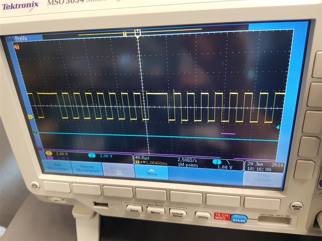
In single SPI transaction I send 0x09 0x00 0x08 (1 byte ADDR, 2 byte DATA), and expect to get back 0x00 0x00 0x08. However, the driver reads back 0x00 0x00 0x60. Below scope screenshot is the MISO, clock, CSEN when viewed from scope, the last byte is clearly 0x08 however the driver has read back 0x60. When changing the bit I get the following transformation:
0x01 (scope) -> 0x01 (driver)
0x02 (scope) -> 0x06 (driver)
0x04 (scope) -> 0x18 (driver)
0x08 (scope) -> 0x60 (driver)
Setup:
- SPI mode is 3 (clock idle high, latch on rising edge), freq 50kHz
- Linux spidev driver, device tree:
0x3a4 (PIN_INPUT | MUX_MODE0) /* spi1_sclk */
0x3ac (PIN_INPUT_PULLDOWN | MUX_MODE0) /* spi1_d0 */
0x3a8 (PIN_OUTPUT_PULLDOWN | MUX_MODE0) /* spi1_d1 */
0x3b0 (PIN_OUTPUT_PULLUP | MUX_MODE0) /* spi1_cs0 */
&mcspi1 {
status = "okay";
pinctrl-names = "default";
pinctrl-0 = <&mcspi1_pins_default>;
ti,spi-num-cs = <1>;
spidev1_0: spidev1@0 {
compatible = "spidev";
reg = <0>;
spi-max-frequency = <20000000>;
spi-cpha;
spi-cpol;
};
};
A snippet of driver registers during the read:
mcspi_write_cs_reg 2C 201103FF
mcspi_read_cs_reg 2C 201103FF
spidev spi1.0: setup: speed 50000, sample trailing edge, clk inverted
mcspi_write_cs_reg 2C 201103FF
mcspi_read_cs_reg 2C 201103FF
mcspi_write_cs_reg 34 3B01
mcspi_read_cs_reg 34 3B01
spidev spi1.0: write-8 09
spidev spi1.0: read-8 00
spidev spi1.0: write-8 00
spidev spi1.0: read-8 00
spidev spi1.0: write-8 08
spidev spi1.0: read-8 60
mcspi_write_cs_reg 34 3B01
mcspi_read_cs_reg 34 3B01
mcspi_write_cs_reg 34 3B00
mcspi_read_cs_reg 34 3B00
mcspi_write_cs_reg 34 0
mcspi_write_cs_reg 2C 201103CB
mcspi_read_cs_reg 2C 201103CB
spidev spi1.0: setup: speed 16000000, sample trailing edge, clk inverted
mcspi_write_cs_reg 34 0
mcspi_read_cs_reg 34 0
Is there anything wrong with my configuration that would case this, or any hints as to the issue? Since the scope is showing correct read out this seems like SPI module / driver is not correctly latching the receive data.
Hi Michail,
In this case I have a peripheral chip connected to AM5728, where AM5728 is the master. The issue is the AM5728 receives data which doesn't align with what has been recorded on scope.
Cheers,
Sean
Hi Michail,
More information, the SPI slave is TI AFE5401-Q1 chip http://www.ti.com/lit/ds/symlink/afe5401-q1.pdf. The use case is programming the AFE chip from AM572x, then reading back the registers to confirm correct configuration has been applied. Section 6.9 of the datasheet describes SPI operations, in particular the read timing:
Section 8.5.1 describes serial interface operation. The original picture shows on the scope the last two data bytes of the MOSI line where the AFE is sending back 0x00 0x08, the MOSI data is stable from negative edge to negative edge of the 50kHz data clock.
Incidentally we also utilize an am335x processor to program AFE chips using very similar pin setup, and we can read back SPI data perfectly on the am335x at same 50kHz and even the same linux driver is used. The am335x driver shows a similar read/write pattern in the driver but works (expect 0xfe 0xf3 on data):
omap2_mcspi_txrx_pio: spidev spi1.0: write-8 09
omap2_mcspi_txrx_pio: spidev spi1.0: read-8 ff
omap2_mcspi_txrx_pio: spidev spi1.0: write-8 fe
omap2_mcspi_txrx_pio: spidev spi1.0: read-8 fe
omap2_mcspi_txrx_pio: spidev spi1.0: write-8 f3
omap2_mcspi_txrx_pio: spidev spi1.0: read-8 f3
Cheers,
Sean
Hello,
in this case it should be a software issue. I will try to investigate.
I noticed that when you get correct data on am335x device you have FF received on MISO during address byte frame.
According to diagram it should be 00. This is not a significant issue though.
I saw a pattern in the wrong data which seems to have some logical explanation.
Looking at bytes from driver's side in binary we have
0x01 (scope) -> 00000001 0x01 (driver)
0x02 (scope) -> 00000110 0x06 (driver)
0x04 (scope) -> 00011000 0x18 (driver)
0x08 (scope) -> 01100000 0x60 (driver)
It seems that driver receives bits with twice the actual frequency (or on both clock edges which may not be the case).
I think SPI receiving part initialization should be double checked. Testing more patterns of data should be also helpful (10h, 20h, 40h).
BR
Michail
Hi Michail,
Apologies for delayed response. Here is a more complete readback from the driver after some experiments, note that some of the values are flipping as the bit shifts more to the left:
0x01 -> 00000001 0x01
0x02 -> 00000110 0x06
0x04 -> 00001100 0x0C
0x04 -> 00011000 0x18
0x08 -> 00011000 0x18
0x08 -> 00110000 0x30
0x08 -> 01100000 0x60
0x10 -> 00110000 0x30
0x10 -> 01100000 0x60
0x10 -> 11000000 0xC0
0x20 -> 11000000 0xC0
0x20 -> 10000000 0x80
0x20 -> 01100000 0x60
0x20 -> 00000000 0x00
0x40 -> 11000000 0xC0
0x40 -> 10000000 0x80
0x40 -> 00000000 0x00
0x80 -> 10000000 0x80
0x80 -> 00000000 0x00
Hello,
in this case I think it should be a configuration issue. Did you try different CPOL, CPHA etc configurations.
Are you using ti-processor-sdk-linux-am57xx-evm-05.02.00.10 ? Asking this because I have it already installed and can take a look at DTS default configuration.
Br
Michail
Found the issue, reflections were occurring on SPI clock line disrupting the am57x internal SPI module. The am5728 datasheet has a note about SPI clock behavior:
This clock signal is implemented as 'pad loopback' inside the device - the output signal is looped back through the input buffer to serve
as the internal reference signal. Series termination is recommended (as close to device pin as possible) to improve signal integrity of the
clock input. Any nonmonotonicity in voltage that occurs at the pad loopback clock pin between VIH and VIL must be less than VHYS
Adding a series termination resistor at 33ohm as close as possible to the CPU resolved the issue. The SPI readback is now behaving as expected.
Marking as resolved in hardware.