This thread has been locked.

If you have a related question, please click the "Ask a related question" button in the top right corner. The newly created question will be automatically linked to this question.

Compiler/BEAGLEBK: PRU MII0

Part Number: BEAGLEBK

Tool/software: TI C/C++ Compiler

Hello!

I have a question about MII_RT (mii0) interface at the BeagleBone Black (Industrial AM3358).

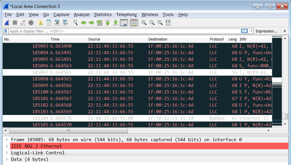
TX doesn't work good (I connect DP83848I ethernet PHY to the BeagleBone Black and can see packets which I send on the WireShark on the PC (via USB to ethernet converter) but there are some packets with shorter length carrying my raw data, in other word some packets are lost partially). 

I use GPI mode as MII_RT, CRC calculated by PRU, enabled auto preamble option and all data (16 bit) are pushed to TX L1 completely by PRU.

Is there any way to check the status of TX L1 to figure out some information about packets byte order, fifo fill level, overwrite occurrence or etc? 

How can i find correlation of parameters like Inter Packet Gap (TX_IPGx), delay between received packet and transmitted packet (TX_START_DELAY) and TX_EN compare timer expiration (TMR_CMP3/4)?

Below is WireShark screen shot of sending process. What happen during sending process?


  • Hi,

    What software is this? Which version? How is the PHY connected to the PRU MII interface?
  • Thank for your reply!

    The above picture is related to WireShark version 2.6.5.

    The compiler is Code Composer Studio version: 8.2.0.00007.

    The connection between PHY and MII0 interface is via expansion header. And the pin-muxing (.gel file) content is in the following:

    // pr1_mii_mt0_clk -> U10 (PIN_GPMC_A0 - mode 5)
    *((unsigned int*) 0x44e10820) = AM335X_PIN_INPUT | 5;

    // pr1_mii0_txd0 -> V13 (PIN_GPMC_A4 - mode 5)
    *((unsigned int*) 0x44e10838) = AM335X_PIN_OUTPUT | 5;

    // pr1_mii0_txd1 -> R12 (PIN_GPMC_A3 - mode 5)
    *((unsigned int*) 0x44e10834) = AM335X_PIN_OUTPUT | 5;

    // pr1_mii0_txd2 -> T12 (PIN_GPMC_A2 - mode 5)
    *((unsigned int*) 0x44e10830) = AM335X_PIN_OUTPUT | 5;

    // pr1_mii0_txd3 -> U12 (PIN_GPMC_A1 - mode 5)
    *((unsigned int*) 0x44e1082c) = AM335X_PIN_OUTPUT | 5;

    // pr1_mii0_rxd0 -> U4 (PIN_GPMC_A8 - mode 5)
    *((unsigned int*) 0x44e108cc) = AM335X_PIN_INPUT | 5;

    // pr1_mii0_rxd1 -> U3 (PIN_GPMC_A7 - mode 5)
    *((unsigned int*) 0x44e108c8) = AM335X_PIN_INPUT | 5;

    // pr1_mii0_rxd2 -> U2 (PIN_GPMC_A6 - mode 5)
    *((unsigned int*) 0x44e108c4) = AM335X_PIN_INPUT | 5;

    // pr1_mii0_rxd3 -> U1 (PIN_GPMC_A5 - mode 5)
    *((unsigned int*) 0x44e108c0) = AM335X_PIN_INPUT | 5;

    // pr1_mii0_txen -> T11 (PIN_GPMC_WPN - mode 5)
    *((unsigned int*) 0x44e10828) = AM335X_PIN_OUTPUT | 5;

    // pr1_mii_mr0_clk -> V4 (PIN_GPMC_A9 - mode 5)
    *((unsigned int*) 0x44e108d8) = AM335X_PIN_INPUT | 5;

    // pr1_mii0_rxdv -> T5 (PIN_GPMC_A10 - mode 5)
    *((unsigned int*) 0x44e108dc) = AM335X_PIN_INPUT | 5;

    // pr1_mii0_rxer -> V3 (PIN_GPMC_A11 - mode 5)
    *((unsigned int*) 0x44e108d4) = AM335X_PIN_INPUT | 5;

    // pr1_mii0_rxlink -> V2 (PIN_GPMC_BE1N - mode 5)
    //*((unsigned int*) 0x44e10878) = AM335X_PIN_INPUT | 5;

    // pr1_mii0_crs -> V5 (PIN_GPMC_CSN3 - mode 2)
    *((unsigned int*) 0x44e108e8) = AM335X_PIN_INPUT | 2;

    // pr1_mii0_col -> T10 (PIN_GPMC_AD9 - mode 5)
    *((unsigned int*) 0x44e10824) = AM335X_PIN_INPUT | 5;

    and I modify .cmd file (in SDK) and add MII_RT memory mapped part.

     PRU_MII_RT_CFG  : org = 0x00032000 len = 0x000000100 CREGISTER=27

    Regards,

  • user5877522 said:
    The connection between PHY and MII0 interface is via expansion header.

    This doesn't sound good, and it may be the root cause for your problems. MII is a 4-bit parallel interface working at 25MHz and the PCB lines need to be short and well equalized in length.