This thread has been locked.

If you have a related question, please click the "Ask a related question" button in the top right corner. The newly created question will be automatically linked to this question.

CCS/AWR1843BOOST: SPIB ChipSelect[0/1/2] switching dosenot work

Part Number: AWR1843BOOST
Other Parts Discussed in Thread: DCA1000EVM

Tool/software: Code Composer Studio

hi

I want to connect 3 devices to SPI_Bport and switch control with ChipSelect[0/1/2].
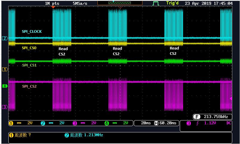
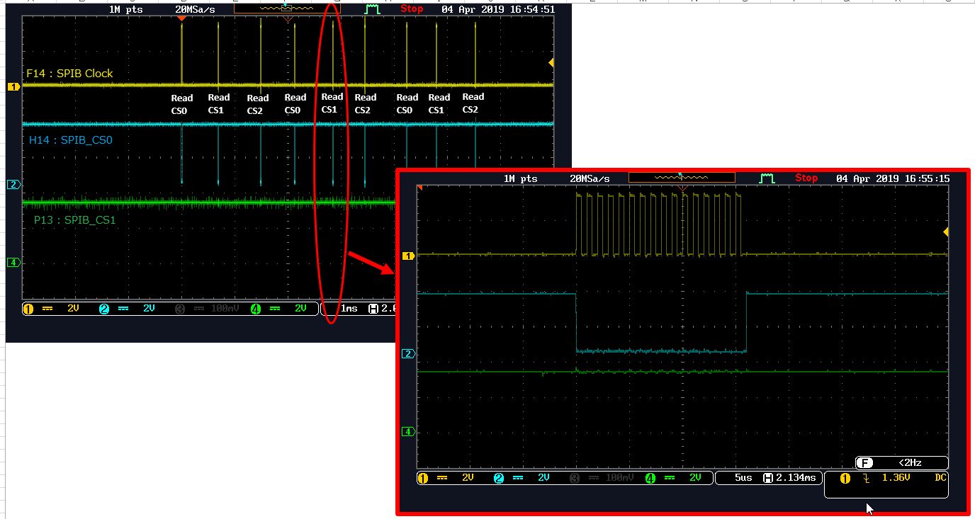
I tried SPI Read while switching ChipSelect CS0/CS1/CS2, but CS0 is always enabled. CS1 and CS2 doesnot work.

Steps
1. Enable SPIB pin settings
  refer : [Pin_Map] and [Pin_MuxSetting]
2. Set SPI parameters.
 refer : [Parameter_Setting]
3. Try to access CS0/CS1/CS2 with SPI_Read command
 a. SPI_Read with CS=0
 b. SPI_Read with CS=1
 c. SPI_Read with CS=2
 Repeat a>b>c.
 refer : [TestCode]
4. As a result of checking the waveform, CS0 is always enabled. Even if it accessed CS1/CS2.

Are there any problems with the procedure for test steps?
or Is there any other root cause?

----------------------------------------------------
Pin_Map
----------------------------------------------------

SPIB-CLK  : F14
SPIB-CS0  : H14
SPIB-CS1  : P13
SPIB-CS2  : J13
SPIB-MOSI : F13
SPIB-MISO : G14

----------------------------------------------------
Pinmux_Setting
----------------------------------------------------

//SPIBCLK 
Pinmux_Set_OverrideCtrl(SOC_XWR18XX_PINF14_PADAJ, PINMUX_OUTEN_RETAIN_HW_CTRL, PINMUX_INPEN_RETAIN_HW_CTRL);
Pinmux_Set_FuncSel(SOC_XWR18XX_PINF14_PADAJ, SOC_XWR18XX_PINF14_PADAJ_SPIB_CLK);
//SPIB CS0
Pinmux_Set_OverrideCtrl(SOC_XWR18XX_PINH14_PADAK, PINMUX_OUTEN_RETAIN_HW_CTRL, PINMUX_INPEN_RETAIN_HW_CTRL);
Pinmux_Set_FuncSel(SOC_XWR18XX_PINH14_PADAK, SOC_XWR18XX_PINH14_PADAK_SPIB_CSN);
//SPIB CS1
Pinmux_Set_OverrideCtrl(SOC_XWR18XX_PINP13_PADAA, PINMUX_OUTEN_RETAIN_HW_CTRL, PINMUX_INPEN_RETAIN_HW_CTRL);
Pinmux_Set_FuncSel(SOC_XWR18XX_PINP13_PADAA, SOC_XWR18XX_PINP13_PADAA_SPIB_CSN1);
//SPIB CS2
Pinmux_Set_OverrideCtrl(SOC_XWR18XX_PINJ13_PADAC, PINMUX_OUTEN_RETAIN_HW_CTRL, PINMUX_INPEN_RETAIN_HW_CTRL);
Pinmux_Set_FuncSel(SOC_XWR18XX_PINJ13_PADAC, SOC_XWR18XX_PINJ13_PADAC_SPIB_CSN2);
// SPIB MISO
Pinmux_Set_OverrideCtrl( SOC_XWR18XX_PING14_PADAI, PINMUX_OUTEN_RETAIN_HW_CTRL, PINMUX_INPEN_RETAIN_HW_CTRL );
Pinmux_Set_FuncSel( SOC_XWR18XX_PING14_PADAI, SOC_XWR18XX_PING14_PADAI_SPIB_MISO );
// SPIB MOSI
Pinmux_Set_OverrideCtrl( SOC_XWR18XX_PINF13_PADAH, PINMUX_OUTEN_RETAIN_HW_CTRL, PINMUX_INPEN_RETAIN_HW_CTRL );
Pinmux_Set_FuncSel( SOC_XWR18XX_PINF13_PADAH, SOC_XWR18XX_PINF13_PADAH_SPIB_MOSI );

----------------------------------------------------
Parameter_Setting
----------------------------------------------------

void spi_init(void)
{
	DMA_Params		DmaParams;
	SPI_Params		params;
	int32_t			errCode = 0;
	uint8_t 		inst = 1;

	DMA_Params_init( &DmaParams );
	gDmaHandle = DMA_open( 0, &DmaParams, &errCode );
	if( gDmaHandle == NULL )
	{
		System_printf( "Open DMA driver failed with error=%d\n", errCode );
		return;
	}

	SPI_init();
	
	SPI_Params_init( &params );
	params.frameFormat = SPI_POL0_PHA0;

	params.dmaEnable = 1;
	params.dmaHandle = gDmaHandle;
	params.eccEnable = 1;

	params.mode = SPI_MASTER;
	params.u.masterParams.bitRate = 1000000; (1MHz)
 
	memset((void *)&params.u.masterParams.slaveProf[0], 0, sizeof(params.u.masterParams.slaveProf));

	params.u.masterParams.numSlaves = 3;
	params.u.masterParams.slaveProf[0].chipSelect = 0;
	params.u.masterParams.slaveProf[0].ramBufLen = MIBSPI_RAM_MAX_ELEM/2;
	params.u.masterParams.slaveProf[0].dmaCfg.txDmaChanNum =0U;
	params.u.masterParams.slaveProf[0].dmaCfg.rxDmaChanNum =1U;
	params.u.masterParams.slaveProf[1].chipSelect = 1;
	params.u.masterParams.slaveProf[1].ramBufLen = MIBSPI_RAM_MAX_ELEM/4;
	params.u.masterParams.slaveProf[1].dmaCfg.txDmaChanNum =2U;
	params.u.masterParams.slaveProf[1].dmaCfg.rxDmaChanNum =3U;
	params.u.masterParams.slaveProf[2].chipSelect = 2;
	params.u.masterParams.slaveProf[2].ramBufLen = MIBSPI_RAM_MAX_ELEM/4;
	params.u.masterParams.slaveProf[2].dmaCfg.txDmaChanNum =4U;
	params.u.masterParams.slaveProf[2].dmaCfg.rxDmaChanNum =5U;

	Spihandle = SPI_open( inst, &params );
	
	if( Spihandle == NULL )
	{
		System_printf("Error: Unable to open the SPI Instance\n");
	}
}

----------------------------------------------------
TestCode :
----------------------------------------------------

int main()
{
...
SPI_Transaction transaction;

transaction.count = 2;
transaction.txBuf = outBuffer;
transaction.rxBuf = inBuffer;
transaction.slaveIndex = 0 or 1 or 2;

SPI_transfer( Spihandle, &transaction )
}

  • I made a mistake in the post.
    I remove this post and migrate to SensorsForum.
    e2e.ti.com/.../790024
  • Hello ,
    The pinmux and other settings seem right.
    Can you please check the below registers in the MIBSPIB when you send the slave 2 and slave 3?
    "SPIDAT1 : CSNR" and "SPIBUF : LCSNR"

    -Raghu
  • Hello,

    I dumped Register.please check attached logs.

    case1 : when read SPIB slave2(CS1) 

    case2 : when read SPIB slave3(cs2)

  • Hi,
    Sorry for my delayed reply.

    The configurations in the code seem to be fine. But the register CSNR do not show the right value based on your slave select.

    Can you make sure some of the pinmux are not being overwritten in you code?

    -Raghu
  • Hi,

    I checked again, but pinmux has not been overwritten.
    I have not set up MIBSPIB at all, is this not affecting anything?
  • Hi ,

    I am sorry I do not understand what you mean by "not setup MIBSPIB" ?

    Are you not initializing the MIBSPIB  in your code?

    -Raghu

  • Hi ,
    Are you using your own hardware or the AWR1843BOOST?
    If you are using the AWR1843BOOST then you will need some ECO on the board for the SPIB to be functional.
    Please refer to the schematic of AWR1843BOOST and check the pins for GPIO_0, GPIO_1, MSS_LOGGER for the chip selects and clocks.

    -Raghu
  • Hi,

    I am using [void spi_init (void)] above source code to use the SPI driver.

    but this code does not include MIBSPI initialization.

    ----
    I mean MIBSPI as : 

    ti\mmwave_sdk_03_01_01_02\packages\ti\drivers\spi\src\mibspi_dma.c
    - MIBSPI_init().
    - MIBSPI_open().
    - etc
    ----
    Your test code does not include the above MIBSPI init.

    Is the initialization sequence correct in [void spi_init (void)]?

  • Hi,

    >Are you using your own hardware or the AWR1843BOOST?
    I using AWR1843BOOST Rev-A board.

    >If you are using the AWR1843BOOST then you will need some ECO on the board for the SPIB to be functional.
    What is "some ECO board"?
    For example, "DCA1000EVM"?

    >Please refer to the schematic of AWR1843BOOST and check the pins for GPIO_0, GPIO_1, MSS_LOGGER for the chip selects and clocks.
    Hmm, I referd the schematicn and I am checking the waveform on the chip resistor

    SPIB-CLK : F14 : AR_MSS_LOGGER >> R136
    SPIB-CS0 : H14 : AR_BSS_LOGGER >> R135
    SPIB-CS1 : P13 : AR_HOSTINTR1 >> R64
    SPIB-CS2 : J13 : AR_GPIO_1 >> R72

    Please check it.
  • Hi,
    I would suggest to populate 0 ohm resistors on R164, R9 and R26.


    The Probe:
    SPIB-CLK : F14 : AR_MSS_LOGGER >> R26
    SPIB-CS0 : H14 : AR_BSS_LOGGER >> R31
    SPIB-CS1 : P13 : AR_HOSTINTR1 >> R64
    SPIB-CS2 : J13 : AR_GPIO_1 >> R9

    BR,
    Raghu
  • Hi,
    The J5 and J6 connectors are not connected to anything (Open), so I do not understand what it means to add 0 Ohms resistors.
  • Hi,
    Any update?
    Best Regards,
    -chunzhou
  • Hi Chunzhou,
    Addding 0 Ohm means solder a 0 ohm resistor.

    -Raghu
  • Hi Raghu,
     
    I found that CS[2] worked fine after I changed some SPI parameters and did some tests.
     
    ■ Here is my test procedure:
    1. Change the ramBufLen of CS[2] to MIBSPI_RAM_MAX_ELEM(64).
       ramBufLef of CS[0] and CS[1] are set to 0.
    params.u.masterParams.numSlaves = 3;
    params.u.masterParams.slaveProf[0].chipSelect = 0U;
    params.u.masterParams.slaveProf[0].ramBufLen = 0;
    params.u.masterParams.slaveProf[0].dmaCfg.txDmaChanNum =0U;
    params.u.masterParams.slaveProf[0].dmaCfg.rxDmaChanNum =1U;
    params.u.masterParams.slaveProf[1].chipSelect = 1U;
    params.u.masterParams.slaveProf[1].ramBufLen = 0;
    params.u.masterParams.slaveProf[1].dmaCfg.txDmaChanNum =2U;
    params.u.masterParams.slaveProf[1].dmaCfg.rxDmaChanNum =3U;
    params.u.masterParams.slaveProf[2].chipSelect = 2U;
    params.u.masterParams.slaveProf[2].ramBufLen = MIBSPI_RAM_MAX_ELEM;
    params.u.masterParams.slaveProf[2].dmaCfg.txDmaChanNum =4U;
    params.u.masterParams.slaveProf[2].dmaCfg.rxDmaChanNum =5U;
    

    2. Write SPI on CS[2]

    int main()
    {
    	...
    	SPI_Transaction transaction;
    
    	transaction.count = 2;
    	transaction.txBuf = outBuffer;
    	transaction.rxBuf = inBuffer;
    	transaction.slaveIndex = 2;
    
    	SPI_transfer( Spihandle, &transaction )
    }
    
    ■ Here is the waveform
        CS[2] is now activated.

     
    ■ MIBSPIB register values


    I have a question now.
    Originally I set the following values on CS[0], CS[1] and CS[2].
    params.u.masterParams.slaveProf[0].ramBufLen = MIBSPI_RAM_MAX_ELEM/4;
    params.u.masterParams.slaveProf[1].ramBufLen = MIBSPI_RAM_MAX_ELEM/4;
    params.u.masterParams.slaveProf[2].ramBufLen = MIBSPI_RAM_MAX_ELEM/2;
    
    In this setting, CS[0] is always activated although I tried to use CS[1] or CS[2].
    Is this correct behavior on SPI driver?
     
    Best Regards,
    -chunzhou
     
  • Hi Chunzhou,

    We are checking on this issue.Attached is the driver modification to address some of the multiple slave support. Could you please check and let us know if this resolves your current issue?mibspi_dma.c

  • Hi Raghu,

    Thanks for the new driver and it works fine so far.
    I will check deeply later.

    Best Regards,
    -chunzhou