This thread has been locked.

If you have a related question, please click the "Ask a related question" button in the top right corner. The newly created question will be automatically linked to this question.

PROCESSOR-SDK-AM437X: QSPI flash issue

Part Number: PROCESSOR-SDK-AM437X
Other Parts Discussed in Thread: AM4377

Hello e2e community,

I have a custom board with AM4377 Cortex A processor. This board has a IS25LP080D flash memory connected through QSPI.

The problem is that in Quad and Dual mode write is succesful, but read corrupts every second byte.

In a Single mode it works like expected - read and write are correct!

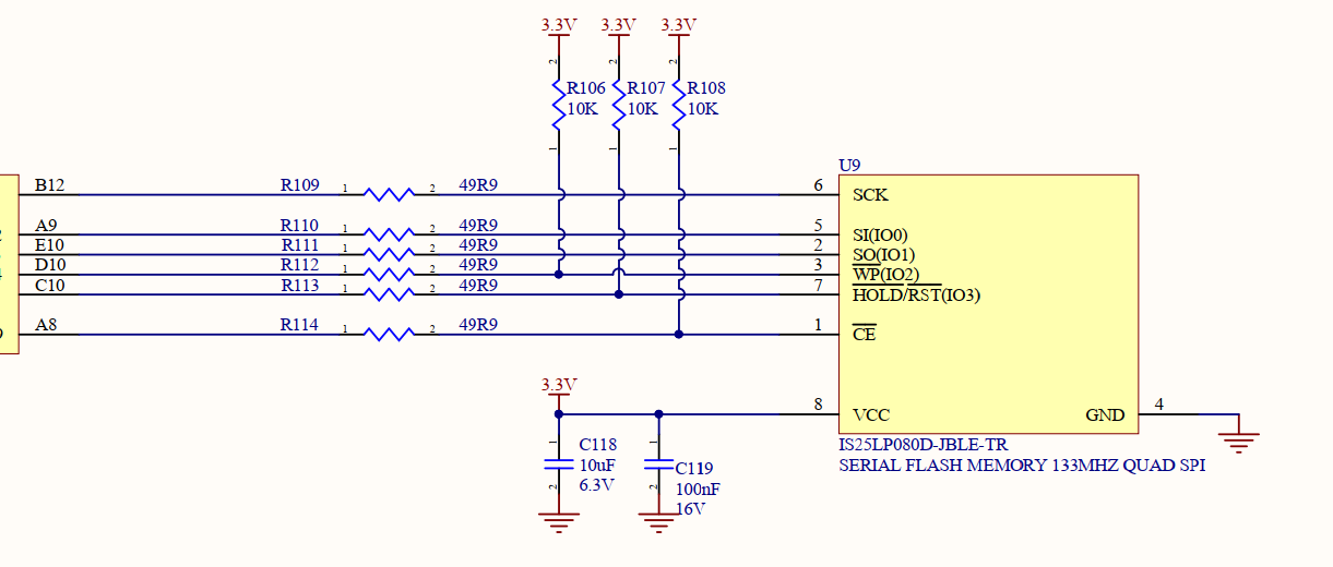
Here is how the the memory is connected:

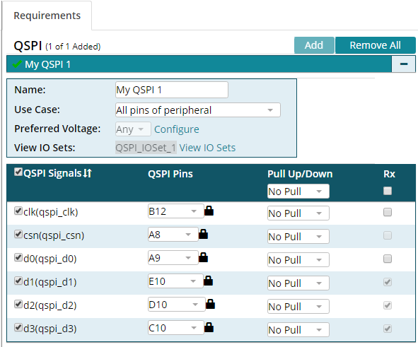
Here is a PinMUX mapping:

Here is what happens in the Quad mode:

txBuf is what I write, rxBuf is what I read back immediatelly after that.

My example is based on the sources found in idkAM437x (qspi_flash.*)

I just corrected the sizes according to the chip specification (IS25LP080D):

/*!
 *  @brief Flash device size in bytes.
 */
#define S25FL_FLASH_DEVICE_SIZE        (1 * 1024 *1024)

/*!
 *  @brief Flash block size in bytes.
 */
#define S25FL_FLASH_BLOCK_SIZE         (64 * 1024)

/*!
 *  @brief Flash sector size in bytes.
 */
#define S25FL_FLASH_SECTOR_SIZE        (4 * 1024)

/*!
 *  @brief Flash device ID.
 */
#define S25FL_FLASH_DEVICE_ID          (0x13)

/*!
 *  @brief Flash device ID.
 */
#define S25FL_FLASH_MFG_ID             (0x9D)
/*!
 *  @brief Macro to enable quad mode.
 */
#define QSPI_FLASH_QUAD_ENABLE_VALUE (0x1)

/*!
 *  @brief Macro indicating the bit position of quad enable bit.
 */
#define QSPI_FLASH_QUAD_ENABLE_BIT   (0x01U)

I'm running the "QSPI_BasicExample_idkAM437x_armExampleProject" as example (but changed the target platform to my board).

Why in Single mode it is OK? Does it mean that wiring is done in a wrong way?

Any thoughts why every second byte could be corrupted are very welcome! I'm running out of ideas what to try next to fix this issue. 

Thank you very much in advance!!!

  • Hi,

    Please check that QSPI_CLK is pinmuxed as required in Note 1 below Table 27-4 in the AM437x TRM Rev. H.
  • Oleg,

    Can you confirm that you erase the QSPI flash prior to programming the QSPI flash. Many of the QSPI vendors require an erase prior to programming of the sector.

    Also check for timing, phase or polarity settings that could impact the setup. Another thing that may also help is if you can verify whether the data coming from the flash is corrupt or whether the data read by the SOC is corrupt. Based on timing you may see the write data on the pin but based on when the data is sampled, there may be errors. 

    Do you consistently see the error on the second byte. Is there any pattern in terms of which bit is corrupt or if the data appears shifted? Are you using normal read or fast read. Have you compared the flash parts on TI EVM and your custom design to see if there are any differences in the read command and its timing.

    Regards,

    Rahul

  • Hello Rahul,

    1. Yes, I erase block in the FLASH before writing

    2. The data in the FLASH is correct I verify in a Single mode - everything is correctly written, corruption happens when I read back in Dual/Quad mode

    3. The flash supports two modes: Mode0 (0,0) and Mode 3 (1,1) - I tried both with the same result

    4. Yes, the pattern is clear, it is always every second byte is corrupted

    5. I use FAST Read function (0x6B)

    /**< Dual Read from QSPI flash device */
    QSPI_LIB_CMD_READ_QUAD = 0x6B,


    6. No, I did not compare flash timings on my board and on the idk, I will give it a try ASAP

  • Hello Biser,

    Thank you for your reply! I remapped CLK pin as shown below:

    Unfortunately it doesn't change anything, I still have problem with the data I read:

    And as you can see from the schematics, I have not a 33 Ohm resistor but a 49.9 Ohm, which I think is about the same:

  • Hi Biser!

    Actually you was right, the problem was in the wrong mapping! I looked how it is done in the IDK_AM437x board and they mark all data pins as RX(2)  and pull up all the pins (1). I did the same and everything works like a charm now!

    What I write is exactly what I readd back!

    Thanks a lot!