This thread has been locked.

If you have a related question, please click the "Ask a related question" button in the top right corner. The newly created question will be automatically linked to this question.

DRA76P: I2C unusual timming

Part Number: DRA76P

Dear Mr/Mrs,

On a custom board based on DRA76P, we are seing unusual retards on the I2C lines. The next captures are from the SDA and SDC lines of i2c1.

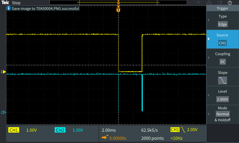
The address of the chip is placed on the bus:

The register to be read is placed on the bus (3ms later!):

We are not even able to see the answer on the oscilloscope:

But for this chip, the answer arrives (and arrives in a proper way). But we are having some problems with a PMIC when kernel is starting, and seems to be a I2C problem... Why are we having this unusual retards on the i2c lines?

Thank you very much!

Best regards.

  • The first scope capture looks as expected (for device address phase of I2C cycle).  The comment is this is for I2C1.  Is this correct?  My understanding is PMICs are on I2C3.

    The 2nd and 3rd scope captures do not provide any helpful information, partly because the scope setup is different from first image.  First image is set for 10uS per division.  The 2nd, 3rd captures are setup for 2ms per division.  The scope captures are zoom'd out too much to see what is happening.

  • Hello Robert,

    As you mention, the first picture shows normal operation on the bus, taking into account a 400kHz clock configuration.

    This captures were taken from u-boot (i2c md command) over i2c1 but the same behaivour has been seen over i2c3. The fact of using i2c1 for this example it is that I am sure about the bus getting a good value when reading from the 0x50 addressed chip (and this chip is placed over i2c1).

    In 2nd and 3rd where you see SCL (yellow) going GND it is captured the "device address phase" shown on the 1st picture and when SCL is going HIGH is the "register selection phase" and the chip answer (now I realize that the 2nd burst seems a little bit longer so I guess that also the chip answer is there).

    How is it possible that from the device addressing to the register selection there is such big delay (more than 3ms)?

    Best regards.

  • I2C supports clock stretching, which is when the slave/target hold the clock low while it retrieves data that master is requesting.  In the scope captures, you can see there is activity on the data line at the beginning of the clock going low (this is likely the address phase).  Then the clock is low for a longer period of time.  This could be the target holding the clock low (clock stretching) util is has the requested data ready to send to master.  Then at the end of the cycle, again it appears there is activity on the data signal - which could be the device responding.