This thread has been locked.

If you have a related question, please click the "Ask a related question" button in the top right corner. The newly created question will be automatically linked to this question.

AM3352: ping fail of RGMII2 in the U-boot

Part Number: AM3352

Dear champs,

My customer is trying to make RGMII2 working in the U-boot but could not succeed to get response when they tried to ping.

Could you please check my customer's configuration in the dts and board.c?

HW is custom board and MII1 was connected to mac0 and RGMII2 was connected to mac1.

SW is Linux Processor SDK 6.1.

In dts,

&mac {
pinctrl-names = "default", "sleep";
pinctrl-0 = <&cpsw_default>;
pinctrl-1 = <&cpsw_sleep>;
dual_emac;
active_slave = <1>;
status = "okay";
};

&davinci_mdio {
pinctrl-names = "default", "sleep";
pinctrl-0 = <&davinci_mdio_default>;
pinctrl-1 = <&davinci_mdio_sleep>;
status = "okay";
};

&cpsw_emac0 {
phy_id = <&davinci_mdio>, <8>;
phy-mode = "mii-txid";
dual_emac_res_vlan = <1>;
};

&cpsw_emac1 {
phy_id = <&davinci_mdio>, <0>;
phy-mode = "rgmii-txid";
dual_emac_res_vlan = <2>;
};

cpsw_default: cpsw_default {
pinctrl-single,pins = <
/* Slave 1 */
0x40 (PIN_OUTPUT_PULLDOWN | MUX_MODE2) /* conf_gpmc_a0.rgmii2_tctl */
0x44 (PIN_INPUT_PULLDOWN | MUX_MODE2) /* conf_gpmc_a1.rgmii2_rctl */
0x48 (PIN_OUTPUT_PULLDOWN | MUX_MODE2) /* conf_gpmc_a2.rgmii2_td3 */
0x4c (PIN_OUTPUT_PULLDOWN | MUX_MODE2) /* conf_gpmc_a3.rgmii2_td2 */
0x50 (PIN_OUTPUT_PULLDOWN | MUX_MODE2) /* conf_gpmc_a4.rgmii2_td1 */
0x54 (PIN_OUTPUT_PULLDOWN | MUX_MODE2) /* conf_gpmc_a5.rgmii2_td0 */
0x58 (PIN_OUTPUT_PULLDOWN | MUX_MODE2) /* conf_gpmc_a6.rgmii2_tclk */
0x5c (PIN_INPUT_PULLDOWN | MUX_MODE2) /* conf_gpmc_a7.rgmii2_rclk */
0x60 (PIN_INPUT_PULLDOWN | MUX_MODE2) /* conf_gpmc_a8.rgmii2_rd3 */
0x64 (PIN_INPUT_PULLDOWN | MUX_MODE2) /* conf_gpmc_a9.rgmii2_rd2 */
0x68 (PIN_INPUT_PULLDOWN | MUX_MODE2) /* conf_gpmc_a10.rgmii2_rd1 */
0x6c (PIN_INPUT_PULLDOWN | MUX_MODE2) /* conf_gpmc_a11.rgmii2_rd0 */

>;
};

in board.c

/* CPSW platdata */
#if !CONFIG_IS_ENABLED(OF_CONTROL)
struct cpsw_slave_data slave_data[] = {
{
.slave_reg_ofs = CPSW_SLAVE0_OFFSET,
.sliver_reg_ofs = CPSW_SLIVER0_OFFSET,
.phy_addr = 8,
},
{
.slave_reg_ofs = CPSW_SLAVE1_OFFSET,
.sliver_reg_ofs = CPSW_SLIVER1_OFFSET,
.phy_addr = 0,
},
};

struct cpsw_platform_data am335_eth_data = {
.cpsw_base = CPSW_BASE,
.version = CPSW_CTRL_VERSION_2,
.bd_ram_ofs = 0x2000,
.ale_reg_ofs = 0xd00,
.cpdma_reg_ofs = 0x800,
.mdio_div = 0xff,
.host_port_reg_ofs = 0x108,
.channels = 8,
.slaves = 2,
.slave_data = slave_data,
.ale_entries = 1024,
.bd_ram_ofs = 0x2000,
.mac_control = 0x20,
.active_slave = 0,
.mdio_base = 0x4a101000,
.gmii_sel = 0x44e10650,
.phy_sel_compat = "ti,am3352-cpsw-phy-sel",
.syscon_addr = 0x44e10630,
.macid_sel_compat = "cpsw,am33xx",
};

struct eth_pdata cpsw_pdata = {
.iobase = 0x4a100000,
.phy_interface = 0,
.priv_pdata = &am335_eth_data,
};

U_BOOT_DEVICE(am335x_eth) = {
.name = "eth_cpsw",
.platdata = &cpsw_pdata,
};
#endif

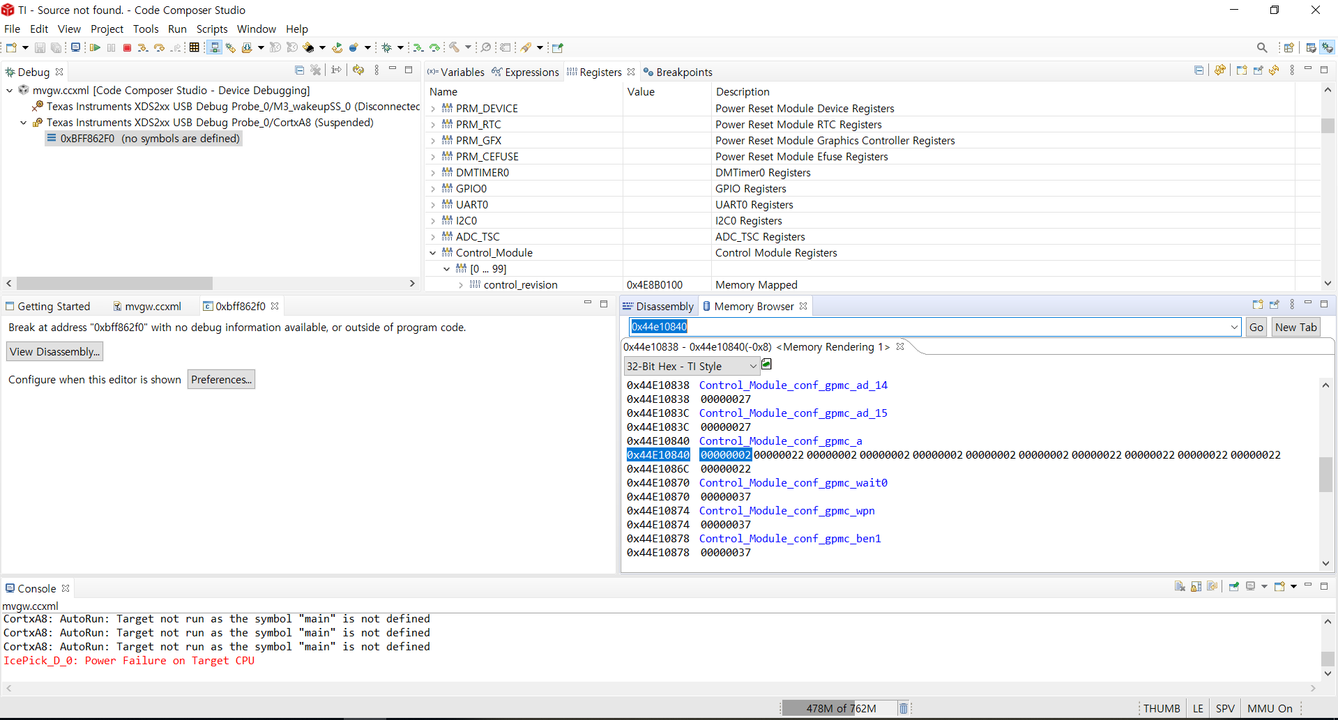
When I checked cpsw_ALE control register, it was all '0' as below, but I think it should be set to '1' in the 'vlan_aware' bit field at least because they should use 'dual mac' mode. is my observation right?

CONTROL 0x00000000

And also, could you please let me know what should be done to make working rgmii2 in the u-boot?

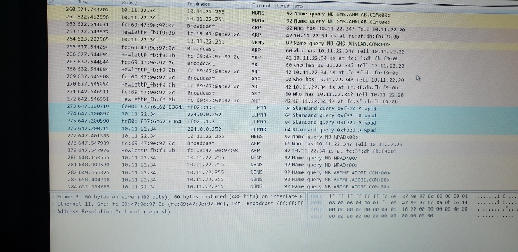
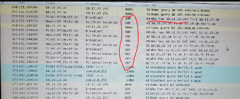
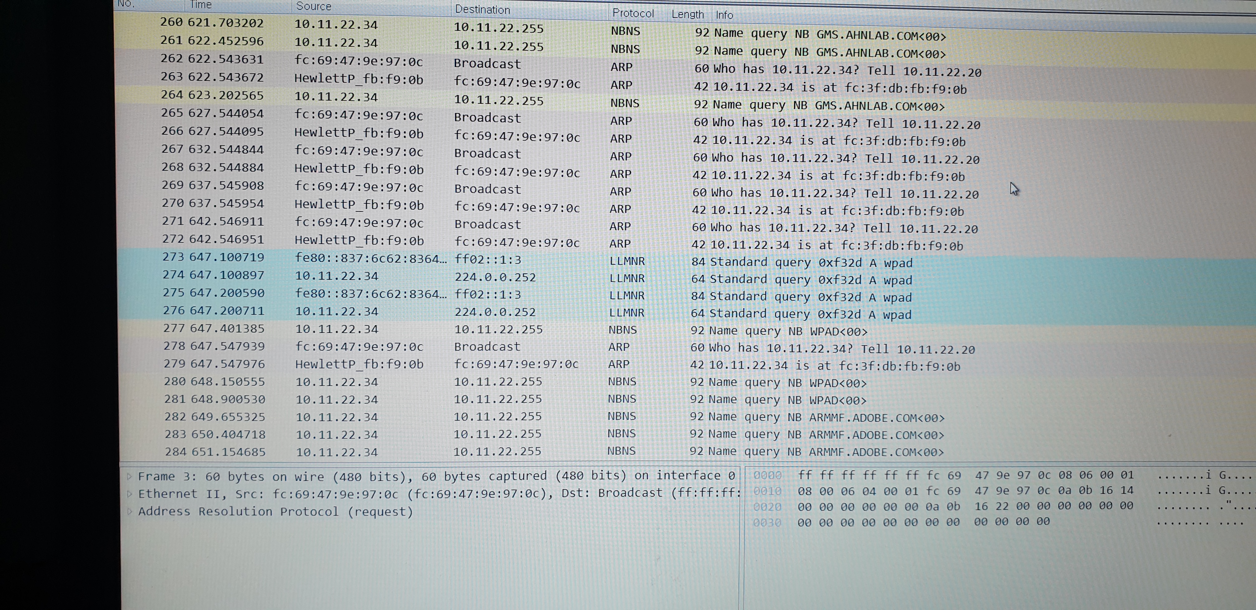
When they tried to ping, there was no response.


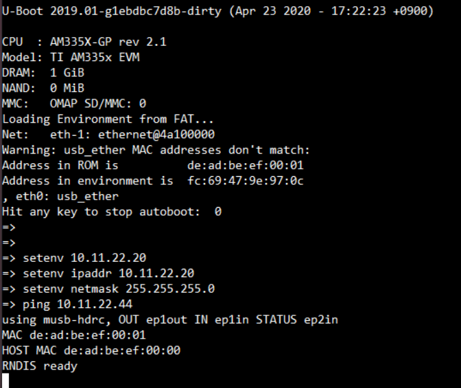
And, I'm curious why 'RNDIS ready' was printed in the console. they just make few modification for their custom board from the u-boot source of PSDK.

Thanks and Best Regards,

SI.

  • Sung-IL said:
    And also, could you please let me know what should be done to make working rgmii2 in the u-boot?

    Assuming the custom board is based on how the AM335x EVM is setup in our SDKv6.x U-Boot this means the pin control driver and associated device tree entries are not used, as CONFIG_PINCTRL and CONFIG_PINCTRL_SINGLE are not set, and the pinmux is actually done via board file instead (mux.c in the board folder). If you want to enable RGMMI2 you could look at other existing boards and see how it is setup. For example doing a quick search I see this...

    a0797059@jiji:~/git/u-boot (ti-u-boot-2019.01-board-port)
    $ git grep 'module_pin_mux.*ii2_pin_mux'
    board/BuR/brppt1/mux.c:static struct module_pin_mux mii2_pin_mux[] = {
    board/BuR/brppt1/mux.c: configure_module_pin_mux(mii2_pin_mux);
    board/compulab/cm_t43/mux.c:static struct module_pin_mux rgmii2_pin_mux[] = {
    board/compulab/cm_t43/mux.c:    configure_module_pin_mux(rgmii2_pin_mux);
    board/siemens/pxm2/mux.c:static struct module_pin_mux rgmii2_pin_mux[] = {
    board/siemens/pxm2/mux.c:       configure_module_pin_mux(rgmii2_pin_mux);
    board/vscom/baltos/mux.c:static struct module_pin_mux rgmii2_pin_mux[] = {
    board/vscom/baltos/mux.c:       configure_module_pin_mux(rgmii2_pin_mux);

    From this it appears board/siemens/pxm2/mux.c might be a good candidate to get some inspiration (it's an AM335x-based board).

    Regards, Andras

  • Hi Andras,

    I checked their mux.c file, but could not find any strange things as below.

    Is there anything to check?

    ~~~~~~~~

    static struct module_pin_mux rgmii2_pin_mux[] = { // ghlee 200414
    {OFFSET(gpmc_a0), MODE(2)}, /* RGMII2_TCTL */
    {OFFSET(gpmc_a1), MODE(2) | RXACTIVE}, /* RGMII2_RCTL */
    {OFFSET(gpmc_a2), MODE(2)}, /* RGMII2_TD3 */
    {OFFSET(gpmc_a3), MODE(2)}, /* RGMII2_TD2 */
    {OFFSET(gpmc_a4), MODE(2)}, /* RGMII2_TD1 */
    {OFFSET(gpmc_a5), MODE(2)}, /* RGMII2_TD0 */
    {OFFSET(gpmc_a6), MODE(2)}, /* RGMII2_TCLK */
    {OFFSET(gpmc_a7), MODE(2) | RXACTIVE}, /* RGMII2_RCLK */
    {OFFSET(gpmc_a8), MODE(2) | RXACTIVE}, /* RGMII2_RD3 */
    {OFFSET(gpmc_a9), MODE(2) | RXACTIVE}, /* RGMII2_RD2 */
    {OFFSET(gpmc_a10), MODE(2) | RXACTIVE}, /* RGMII2_RD1 */
    {OFFSET(gpmc_a11), MODE(2) | RXACTIVE}, /* RGMII2_RD0 */
    {OFFSET(mdio_data), MODE(0) | RXACTIVE | PULLUP_EN},/* MDIO_DATA */
    {OFFSET(mdio_clk), MODE(0) | PULLUP_EN},/* MDIO_CLK */
    {-1},
    };

    static struct module_pin_mux mii1_pin_mux[] = {
    {OFFSET(mii1_rxerr), MODE(0) | RXACTIVE}, /* MII1_RXERR */
    {OFFSET(mii1_txen), MODE(0)}, /* MII1_TXEN */
    {OFFSET(mii1_rxdv), MODE(0) | RXACTIVE}, /* MII1_RXDV */
    {OFFSET(mii1_txd3), MODE(0)}, /* MII1_TXD3 */
    {OFFSET(mii1_txd2), MODE(0)}, /* MII1_TXD2 */
    {OFFSET(mii1_txd1), MODE(0)}, /* MII1_TXD1 */
    {OFFSET(mii1_txd0), MODE(0)}, /* MII1_TXD0 */
    {OFFSET(mii1_txclk), MODE(0) | RXACTIVE}, /* MII1_TXCLK */
    {OFFSET(mii1_rxclk), MODE(0) | RXACTIVE}, /* MII1_RXCLK */
    {OFFSET(mii1_rxd3), MODE(0) | RXACTIVE}, /* MII1_RXD3 */
    {OFFSET(mii1_rxd2), MODE(0) | RXACTIVE}, /* MII1_RXD2 */
    {OFFSET(mii1_rxd1), MODE(0) | RXACTIVE}, /* MII1_RXD1 */
    {OFFSET(mii1_rxd0), MODE(0) | RXACTIVE}, /* MII1_RXD0 */
    {OFFSET(mdio_data), MODE(0) | RXACTIVE | PULLUP_EN}, /* MDIO_DATA */
    {OFFSET(mdio_clk), MODE(0) | PULLUP_EN}, /* MDIO_CLK */
    {-1},
    };

    When I checked 'board/siemens/pxm2/mux.c file, I found some pins(gpmc_a6, gpmc_a9) were set to gpio, not rgmii2 as below.

    Does my understanding right?

    ~~~~

    static struct module_pin_mux rgmii2_pin_mux[] = {
    {OFFSET(gpmc_a0), MODE(2)}, /* RGMII2_TCTL */
    {OFFSET(gpmc_a1), MODE(2) | RXACTIVE}, /* RGMII2_RCTL */
    {OFFSET(gpmc_a2), MODE(2)}, /* RGMII2_TD3 */
    {OFFSET(gpmc_a3), MODE(2)}, /* RGMII2_TD2 */
    {OFFSET(gpmc_a4), MODE(2)}, /* RGMII2_TD1 */
    {OFFSET(gpmc_a5), MODE(2)}, /* RGMII2_TD0 */
    {OFFSET(gpmc_a6), MODE(7)}, /* RGMII2_TCLK */
    {OFFSET(gpmc_a7), MODE(2) | RXACTIVE}, /* RGMII2_RCLK */
    {OFFSET(gpmc_a8), MODE(2) | RXACTIVE}, /* RGMII2_RD3 */
    {OFFSET(gpmc_a9), MODE(7)}, /* RGMII2_RD2 */
    {OFFSET(gpmc_a10), MODE(2) | RXACTIVE}, /* RGMII2_RD1 */
    {OFFSET(mdio_data), MODE(0) | RXACTIVE | PULLUP_EN}, /* MDIO_DATA */
    {OFFSET(mdio_clk), MODE(0) | PULLUP_EN}, /* MDIO_CLK */
    {-1},
    };

    Thanks and Best Regards,

    SI.

  • Hi Andras,

    I checked control register for gpmc_a0~11 and found the modes were set to '02' properly, but still failed in ping as below.

    It seems the negotiation with PC was done well and I found the connection was changed as 100Mbps when the speed was changed in the PC setting.

    When I checked CPSW_ALE control register, I found c still was not set and all bits are zero.

    Is it right ale_vlan_aware bit should be set to enable RMII2 in uboot?

    In their test, they just enabled RGMII2 only just for test to make clear RGMII pinmux setting as below.

    ~~~~~~~~~

    } else if (board_is_customer()) { 
    //configure_module_pin_mux(mii1_pin_mux);
    configure_module_pin_mux(rgmii2_pin_mux);

    Thanks and Best Regards,

    SI.

  • SI,

    just to confirm, their first network interface is working as expected, it's just the second one (RGMII2) that they have trouble with? Is this the same issue on all of their boards of that type, assuming there is more than one?

    Before digging a bit deeper, a common reason for the connection not working is an improper "phy-mode" DTS setting. Can you please experiment with the associated setting as suggested in this E2E post https://e2e.ti.com/support/processors/f/791/p/894279/3314324#3314324 and report back.

    If that still doesn't help please share schematic extract showing the connections between the AM335x SOC and the PHY, plus the circuitry around the PHY, so I can double-check this piece.

    Regards, Andreas

  • Hi Andreas,

    No.this issue was occurred at their board bring-up and they are testing only one board now.

    They have not tested it in other boards and I did not check if there are other boards.

    And they also have not tested the first network interface as it is connected to FPGA via MII interface.

    I'll check the phy-mode as you recommended.

    BTW, how about dual-mode setting? Should they be done dual-mode setting?

    If so, how they can confirm if they set dual-mode properly? 

    Thanks and Best Regards,

    SI.

  • Hi Adreas,

    When they checked the network log, they found there was no progress after ARP packet.

    Could you please check their HW schematic?(ping.zip) Do you think there is still an issue in their setup of PHY in their UBOOT SW?

    ping.zip

    Please check below network log also.

    Thanks and Best Regards,

    SI.

  • SI,

    thanks for the additional info and the schematic. Please give me a day to review things in a bit more detail.

    As for the ARP request, I can't see anything on that screenshot. The important thing is, do you see the board sending out an ARP request packet (note that U-Boot will never respond to incoming ARP requests)?

    Have you heard back from the suggested phy-mode experiments?

    Also can you see if they can build up and test a second board, so we know that the issue occurs consistently, and is not an outlier?

    Regards, Andreas

  • Hi Adreas,

    Yes. we believe the board sending out an ARP request packet, but the U-Boot will never response to incoming ARP requests.

    And, unfortunately I heard there was no improvement in the phy-mode experiments.

    We found ARP requests in below, but there was no response in the U-Boot.

    the ip address of PC is 10.11.22.34 and the target custom board is 10.11.22.20 in below.

    Thanks and Best Regards,

    SI.

  • Was there any further information on this? I'm running into the same problem, with the same chip. 

  • Suresh Joshi1 said:
    Was there any further information on this? I'm running into the same problem, with the same chip. 

    I saw you opened a related E2E post here: https://e2e.ti.com/support/processors/f/791/t/902359

    I'm going to assign that other thread to myself as well.

    Regards, Andreas

  • Hi Andreas,

    Is there any update?

    I uploaded again the log of wire shark in below.

    Fc:69:47:~~~ is the AM3352 target board and hewlettP_fb:~~ is the PC.

    Thanks and Best Regards,

    SI.

  • SI,

    thanks that screenshot is a lot better, and the ARP request/responses are visible.

    I reviewed the HW, and it looks okay I think. It seems aligned with http://www.ti.com/tool/TIDA-00204 which was probably used as a reference for the design I suppose?

    A couple of points:

    • I can't find a datasheet for the magnetic RJ45 connector (CON4) but I noticed that the TRDC- signal is connected to the TXD3+ signal, and vice versa. All other signal pairs have "-" connected to "-", and "+" connected to "+". It could be possible that there is a connection issue here. I've experienced this myself in the past that networking was not working because of a mis-wired connector or magnetic. Sometimes it can be made work (for testing) by cutting an Ethernet cable, and re-arranging the wire pairs (trying different combinations). I've had success with that in the past, but it probably isn't a workaround for all possible mis-wirings that can happen.
    • is the CONFIG_PHY_TI option turned on in U-Boot? It's a dedicated driver for the DP83867 PHY, which also reads a variety of device tree properties for configuration purposes, see example boards using git grep -i DP83867 arch/arm/dts/  and also check the DTS bindings document at doc/device-tree-bindings/net/ti,dp83867.txt.
    • Note that the reference design has strap resistors on RX_D6 to configure RGMII mode, whereas the customer design has not. But the PHY device driver should be able to take care of this too via dp83867_config(). Might be worth adding some printf()s to that function to make sure the right code path is being executed.


    I'm also going to check with one of my colleagues who is more of a networking domain expert to see if it can read something from the symptoms. 

    Regards, Andreas

  • Hi Andreas,

    Have you checked with your colleagues on this issue?

    My customer also found tx clock was not changed even when change connection modes(10/100/1000) in the PC although RX clock was changed properly.

    Do you have any idea what should be checked further in this case?

    If we found below code was worked, can we assume the driver was worked well?

    in the drivers/net/phy/ti.c, dp83867_config(),

    else if (phy_interface_is_sgmii(phydev)) {

    :

    printf("RGMII config");

    :

    }

    Thanks and Best Regards,

    SI.

  • SI,

    Sung-IL said:
    Do you have any idea what should be checked further in this case?

    Since you are trying to setup two network interfaces, make sure you have the right one selected for your tests. Sounds like at least earlier you had issues with that as U-Boot was trying to probe an USB-based network interface (as evident from the 'RNDIS' prints). There is some information here on selecting network interfaces in U-Boot that might be worth double-checking:

    https://stackoverflow.com/questions/32747239/can-u-boot-support-more-than-one-ethernet-port

    Sung-IL said:
    Have you checked with your colleagues on this issue?

    It was suggested as another data point to try using the Linux Kernel to see if the network interface can be probed and initialized properly as the use of U-Boot may not always be straightforward due to additional complexities with pinmux, DTS vs. platform-data based configuration, and also if there is more than one network interface involved. Btw U-Boot doesn't consider certain advanced DTS properties like 'dual_emac' for example. Using Linux will also bring additional diagnostic capabilities such as via 'ethtool'.

    Sung-IL said:

    else if (phy_interface_is_sgmii(phydev)) {

    :

    printf("RGMII config");

    :

    }

    I looked at that code, if you really inside https://git.ti.com/cgit/processor-sdk/processor-sdk-u-boot/tree/drivers/net/phy/ti.c?h=processor-sdk-u-boot-2019.01#n357 that sounds like you are testing positive for SGMII? Why would you be printing "RGMII config" inside the SGMII check code path??

    Regards, Andreas

  • Hi Andreas,

    Sorry for your confusing.

    DP83867 was connected to RGMII1 port of AM3352 in my customer's board. They did not used RNDIS and the RNDIS was not print now.

    And, also it was my typo and I meant I inserted printf() in the below RGMII code.

    if (phy_interface_is_rgmii(phydev)) {

    :

    printf("RGMII config");

    :

    }

    Thanks and Best Regards,

    SI.

  • Sung-IL said:

    Sorry for your confusing.

    DP83867 was connected to RGMII1 port of AM3352 in my customer's board. They did not used RNDIS and the RNDIS was not print now.

    And, also it was my typo and I meant I inserted printf() in the below RGMII code.

    Okay. I think the best is to now move to trying to use the Kernel to see if the network I/F can be made work. If so, we'll then go back and see why U-Boot wasn't working.

    Regards, Andreas

  • Hi Andreas,

    Thanks for your confirm. BTW, I failed to add printf() in the dp83867_config() function(drivers/net/phy/ti.c).

    So, I tried to add printf in the u-boot for AM3352 SK EVM just for test, but still failed.

    Even when I added printf() in the board_init()(board/ti/am335x/board.c), I could not see any output in the terminal.

    I checked below e2e and added "#define DEBUG" in the top of the file, but could not find any my print as below.

    https://e2e.ti.com/support/processors/f/791/p/864659/3219156#3219156

    Could you please what should be modified to add printf() in the U-boot?

    My log is

    0
    switch to partitions #0, OK
    mmc0 is current device
    SD/MMC found on device 0
    ** Unable to read file boot.scr **
    751 bytes read in 5 ms (146.5 KiB/s)
    Loaded env from uEnv.txt
    Importing environment from mmc0 ...
    " (type: i)lags type check failure for "serverip" <= "192.168.0.41
    " into hash tableinsert "serverip=192.168.0.41
    " (type: i)lags type check failure for "ipaddr" <= "192.168.0.141
    " into hash tableinsert "ipaddr=192.168.0.141
    " (type: i)lags type check failure for "netmask" <= "255.255.255.0
    " into hash tableinsert "netmask=255.255.255.0
    Running uenvcmd ...
    Unknown command 'dcache' - try 'help'
    Unknown command 'icache' - try 'help'
    Unknown command 'us' - try 'help'
    ethernet@4a100000 Waiting for PHY auto negotiation to complete. done
    link up on port 1, speed 1000, full duplex
    *** ERROR: `serverip' not set
    bootm - boot application image from memory

    Thanks and Best Regards,

    SI.

  • Sl,

    can you please move to using the Kernel for testing as suggested earlier. That's usually the most straightforward method to bring up and prove out the interface. Thanks.

    Sung-IL said:

    So, I tried to add printf in the u-boot for AM3352 SK EVM just for test, but still failed.

    Even when I added printf() in the board_init()(board/ti/am335x/board.c), I could not see any output in the terminal.

    Also as for U-Boot, adding prints may not always work depending on how far along you are in the initialization sequence, as printing requires the serial console to have gotten activated in that respective stage of U-Boot. Usually what helps here is enabling CONFIG_DEBUG_UART* in U-Boot, see here for details: e2e.ti.com/.../3351094

    Regards, Andreas

  • Hi Andreas,

    Thanks for your response.

    I discussed with my customer to move to Linux Kernel, but concluded that it will be hard for them because there is only UART to upload Kernel in uboot.

    I also found tx clock was not changed well although rx clock was changed along with 10/100/1000 mode change. e.g. When they set the PC to 1G bps mode, the TX clock of DP83867 to AM3352 in their target board was set to 125Mhz, and then it was changed to 25Mhz at 100Mbps mode, but was not changed to 2.5Mhz at 10Mbps. Do you think there is an issue between GMAC of AM3352 and DP83867?

    Thanks and Best Regards,

    SI.

  • Sung-IL said:
    I discussed with my customer to move to Linux Kernel, but concluded that it will be hard for them because there is only UART to upload Kernel in uboot.

    Okay. So no SD card interface of any sorts?

    Sung-IL said:
    Do you think there is an issue between GMAC of AM3352 and DP83867?

    I'll be out of the office until around m/o to e/o next week but I asked one of my colleagues to see if he can have a look at this thread and potentially offer additional suggestions.

    Regards, Andreas

  • Sung-IL said:
    When they set the PC to 1G bps mode, the TX clock of DP83867 to AM3352 in their target board was set to 125Mhz, and then it was changed to 25Mhz at 100Mbps mode, but was not changed to 2.5Mhz at 10Mbps

    I see you are using U-Boot 2019.01, but can you check if you have the following commit in your tree:

    net: ti: cpsw: enable 10Mbps link speed support in rgmii mode
    https://git.ti.com/cgit/processor-sdk/processor-sdk-u-boot/commit/drivers/net/ti/cpsw.c?h=processor-sdk-u-boot-2019.01&id=a1578d58b46efddd889a5b335885c5b1d3498b52

    Sung-IL said:
    I also found tx clock was not changed well although rx clock was changed along with 10/100/1000 mode change

    If I look at the PHY datasheet it seems like the GTX_CLK signal (input to the PHY) is always 125MHz as per "Pin Functions" table, so assuming that this is what you measured I don't think that is an issue. But if you can you could probe the "TX_CLK" signal, which should reflect the link speed.

    A lot of things seem to be working already as you can send out ARP requests and see them on the other side. I'm checking again with my colleague once again but to me it seems like this could be a hardware issue. You mentioned only one board was built, so I'd try to get another one setup to have another data point. Then, it might be worth probing the RX_Dx signals on the PHY with an oscilloscope to see if there is activity during ARP/ARP response. Also have you tried re-arranging the Ethernet wires to see if that makes a difference?

    Regards, Andreas

  • Also from your earlier post...

    Sung-IL said:
    struct cpsw_platform_data am335_eth_data = {
    .cpsw_base = CPSW_BASE,
    .version = CPSW_CTRL_VERSION_2,
    .bd_ram_ofs = 0x2000,
    .ale_reg_ofs = 0xd00,
    .cpdma_reg_ofs = 0x800,
    .mdio_div = 0xff,
    .host_port_reg_ofs = 0x108,
    .channels = 8,
    .slaves = 2,
    .slave_data = slave_data,
    .ale_entries = 1024,
    .bd_ram_ofs = 0x2000,
    .mac_control = 0x20,
    .active_slave = 0,
    .mdio_base = 0x4a101000,
    .gmii_sel = 0x44e10650,
    .phy_sel_compat = "ti,am3352-cpsw-phy-sel",
    .syscon_addr = 0x44e10630,
    .macid_sel_compat = "cpsw,am33xx",
    };

    I was discussing about this with my colleague and noticed that you have the active_slave field in the platform data set to 0. While it is set to 1 in your DTS which is the right setup for DTS for what you are trying to do with using the second network interface, our standard AM335x EVM based U-Boot setup (which I suppose you based your board port on) doesn't use the DTS to setup this parameter, but rather uses the platform data. So can you try setting setting .active_slave = 1 here and see what that does.

    Regards, Andreas

  • Hi Andreas,

    Unfortunately it was not helped in our case and the ping was still failed even when my customer modified to '.active_slave = 1'.

    But, I found they used DP83867 PHY chip in their previous project also and suggested to test their SW configuration on that board, and they found it works well.

    So, my customer concluded there is a HW issue in their current board and they will build 2nd board with more careful layout design, and I would like to close this thread.

    Thanks for your great helps on this issue.

    Thanks and Best Regards,

    SI.

  • Sung-IL said:
    they will build 2nd board with more careful layout design, an

    Thanks for the update. I'm not convinced a layout change will magically fix things, but it is certainly worth a try. There could be some other kind of assembly/manufacturing issue at play here so I would just build up another board based on the existing design to re-try, rather than re-doing the board design (high effort). Just my two cents.

    Regards, Andreas