This thread has been locked.

If you have a related question, please click the "Ask a related question" button in the top right corner. The newly created question will be automatically linked to this question.

AM5728: Need help with DSP/C66x controlled MMC1 Host controller and connected SDIO (I/O only) Device

Part Number: AM5728
Other Parts Discussed in Thread: SYSBIOS, SYSCONFIG

We are working on a custom board with AM5728 SoC. From the mentioned post (e2e.ti.com/.../892681) we are working towards writing SDIO stack using the MMCx CSL routines with pdk_am57xx_1_0_10 package, as there is no support for SDIO on C66x/DSP side and only SD/MMC support is present.

On the custom board SDIO (I/O only) device is connected to MMC1 and once initialize/enumerated, only block transfer from host-to-device is the needed with both EDMA and Interrupt support from the CSL routines.

I have used the CSL routines for MMC1 (baseaddr @ 0x4809C000) to initialize the controller using MMCSD_v1_open(), but when the first SDIO command CMD52 is sent for I/O reset of the SDIO device using MMCSD_v1_transfer, I see that command fails with timeout error and HS_MMCSD_INTR_MASK_ERR.HS_MMCSD_INTR_MASK_CMDTIMEOUT register bit is set.

Below are a few more observations,
1. Tested sending CMD52 with interrupt enabled in one run and interrupt disabled in second run by properly setting 'enableInterrupt' in MMCSD_v1_HwAttrs structure. In both the cases, I see the command is timing out

2. I probed the MMC1_CMD and MMC1_CLK lines on the board and I see that neither of them is toggling when the command is submitted to the controller. This in a way explains why the command timed out, but now I am not sure why the lines are not toggling

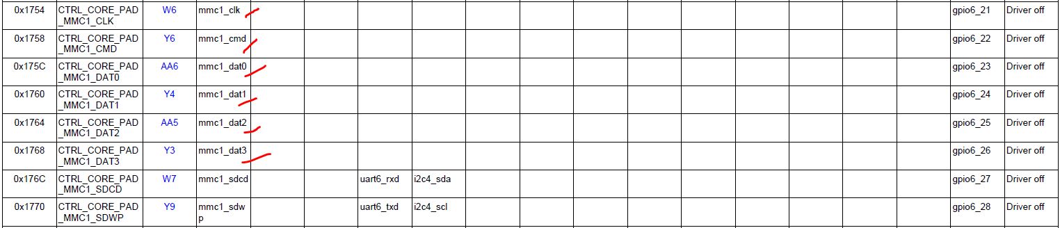
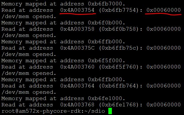
3. I checked the Pinmux configuration of the MMC1 pins W6, Y6, AA6, Y4, AA5 & Y3. W7 and Y9 are not configured as our SDIO device is I/O only. I see that all six pins have pinmux configuration value of 0x00060000, ie, all are in MMC1 mode with MMC1_CLK_PULLTYPESELECT and MMC1_CLK_ACTIVE register bits set. Below are the references.

4. During Host controller initialization of MMC1, I saw that inputClk & outputClk were configured to 96MHz & 4MHz, but the inputClockControl routine (as defined in MMCSD_soc.c) picked 192MHz as system configured clock. I am assuming this part is fine as the MMC1 host controller initialization completed without any issues and it was ready to issue first SDIO CMD52 to the device. I see this print "Input clock[192000000] to MMC is different from what is set in hwAttrs" from MMCSD_v1.c file.

With Pinmux being right and Host controller getting initialized properly what more am I missing on C66x/DSP side to get the communication started. Please note, I have removed all references of MMC1 from the ARM side Device-tree to prevent any conflict between ARM and DSP.

Any inputs getting the Clk and Command line to toggle and getting the initial commands to start working will be helpful.

thanks--

Somesh

  • Additional update on the issue.

    Tested this at Uboot level. I configured the mmc_clk1 (0x1754) pin to gpio6_21 by writing CTRL_CORE_PAD_MMC1_CLK (0x4A00_3754) register to 0xE. With this PinMux update, GPIO_OE (0x4805_D134) register was cleared to make complete GPIO6 bank pins to output and toggling all bits on GPIO_DATAOUT (0x4805_D13C) register toggles the probe point being checked for MMC1_CLK line.

    I am assuming this observation rules out any hardware connectivity issues, atleast till the probe point on the board. Now beyond Uboot, after ARM boots up Linux and loads DSP firmware for MMC1 configuration I am not able to pin point what configuration maybe going wrong.

    If I try to repeat the above test executed at Uboot level on Linux using devmem2, I see L3 violation messages being dumps on ARM/Linux console. Does this mean there is still some conflict in configuration between ARM/Linux and DSP/Sysbios?

  • Update on the thread.

    With MMC1_CLK/MMC1_CMD lines configured as GPIO6_21/GPIO6_22, I was able to toggle these lines from both Linux and from DSP. I do not see any crashes OR inconsistencies when CTRL_CORE_PAD_MMC1_CMD (0x4A003758) and CTRL_CORE_PAD_MMC1_CLK (0x4A003754) are configured as GPIO pins and these lines are toggled using GPIO_OE/GPIO_DATAOUT registers.

    While ARM is using MMC2 Host controller to talk to connected eMMC card, is it possible for DSP to use MMC1 Host controller to talk to a connected SDIO device? If yes, then I think there are still some modules active on ARM side that may be holding the MMC1 pins and not allowing DSP to use them. Any suggestion on how to continue on this will be helpful.

  • Someshwar, 

    Are you initializing the MMC1 module correctly?  Did the CLK toggle for other commands or do you not see CLK toggling at all?  Sounds like your CLK or voltage may not be setup correctly.  MMC1 has a PBIAS register that has to be set based on the interfacing voltage.  Please dump values of all MMC1 registers as well as CTRL_CORE_CONTROL_PBIAS, and the interfacing voltage SDIO is operating under.

    Please also make sure you are setting the correct IODelay setting for the speed mode you are interfacing at.

    Have a great day!

    Best Regards,

    Shiou Mei

  • Hi Shiou Mei. Thanks for your response.

    Yes, the MMC1 Host controller is initialized properly. When I load the DSP program from JTAG, then I see the first command being sent and MMC1_CLK and MMC1_CMD lines toggling. But when I load the same program from ARM/Linux using remoteproc, then I do not see the lines toggling.

    With ARM using MMC2 to talk with connected eMMC and DSP accessing MMC1 to talk to connected SDIO, is it possible for both these cores to simultaneously access their respective MMC Host controllers? I had posted this query at this link (https://e2e.ti.com/support/processors/f/791/t/934685). It will help if you can confirm this. While ARM can successfully talk to eMMC card over MMC2, DSP is not able to toggle SDIO device over MMC1 when loaded using remoteproc.

    I have disabled the mmc@4809C000 from the Linux Device-tree and corresponding MMC1 clocks. The MMC1 lines are operating at 3.3V, but our SDIO device is operating at 1.8V, we have a level translator sitting between the MMC1 Host controller lines and our SDIO Device. Below is the schematic snapshot of the level translator chip from TI. I am probing for MMC1_CLK and MMC1_CMD lines at R1001 and R1000 resistors towards Host Controller side.

    I will provide the dump of MMC1 register values and the CTRL_CORE_CONTROL_PBIAS tomorrow so that you can verify them.

    thanks--

    Someshwar

  • Hi Shiou Mei,

    Below is the dump of MMC1 registers after the first SD command failed.

    Core Control Module:
    (0x4A002E00) CTRL_CORE_CONTROL_PBIAS :0xd200000

    MMC1 Host Controller regs:
    (0x480BC000) MMCHS_HL_REV :0x96579b34
    (0x4809C004) MMCHS_HL_HWINFO :0x4b
    (0x4809C010) MMCHS_HL_SYSCONFIG :0x28
    (0x4809C110) MMCHS_SYSCONFIG :0x2015
    (0x4809C114) MMCHS_SYSSTATUS :0x1
    (0x4809C124) MMCHS_CSRE :0x0
    (0x4809C128) MMCHS_SYSTEST :0x8000
    (0x4809C12C) MMCHS_CON :0x681
    (0x4809C130) MMCHS_PWCNT :0x0
    (0x4809C134) MMCHS_DLL :0x80000000
    (0x4809C200) MMCHS_SDMASA :0x0
    (0x4809C204) MMCHS_BLK :0x200
    (0x4809C208) MMCHS_ARG :0x40ff8000
    (0x4809C20C) MMCHS_CMD :0x1020000
    (0x4809C210) MMCHS_RSP10 :0x0
    (0x4809C214) MMCHS_RSP32 :0x0
    (0x4809C218) MMCHS_RSP54 :0x0
    (0x4809C21C) MMCHS_RSP76 :0x0
    (0x4809C220) MMCHS_DATA :0x0
    (0x4809C224) MMCHS_PSTATE :0x10000
    (0x4809C228) MMCHS_HCTL :0xd10
    (0x4809C22C) MMCHS_SYSCTL :0xe3c87
    (0x4809C230) MMCHS_STAT :0x20018000
    (0x4809C234) MMCHS_IE :0x307f0033
    (0x4809C238) MMCHS_ISE :0x0
    (0x4809C23C) MMCHS_AC12 :0x0
    (0x4809C240) MMCHS_CAPA :0x22e90080
    (0x4809C244) MMCHS_CAPA2 :0xf77
    (0x4809C248) MMCHS_CUR_CAPA :0x0
    (0x480BC250) MMCHS_FE :0x96579b34
    (0x4809C254) MMCHS_ADMAES :0x0
    (0x4809C258) MMCHS_ADMASAL :0x0
    (0x4809C260) MMCHS_PVINITSD :0x401e0
    (0x4809C264) MMCHS_PVHSSDR12 :0x40002
    (0x4809C268) MMCHS_PVSDR25SDR50 :0x10002
    (0x4809C26C) MMCHS_PVSDR104DDR50 :0x20000
    (0x4809C2FC) MMCHS_REV :0x33020000

    These values were read from DSP1. Do you see any problems with the configuration?

    I am attaching the Linux Device-tree source file as well for you to verify.

    The original question still remains. Can ARM access MMC2 and DSP access MMC1 Host controllers simultaneously?

    thanks--

    Somesh

    Device-tree attachment

    devicetree-uImage-am572x-phycore-rdk-op3-sdio.dts.txt

  • Somesh,

    Since the MMC modules are separate there shouldn't be any issues.  However, your code could potentially be writing to the same memory region or trying to access the same registers; did you write the SW based on PDK examples, or are you running the SW code as is?

    Based on PSTATE status, your CMD and DAT signals are all held at 0.  This will cause the host controller to think the line is busy and halt all outgoing operations.  Please check if the signals (esp DAT0) are indeed 0 with an oscilloscope, and if so, if the pulls or the pinmux settings are not registering properly.

    The PBIAS register value looks okay.

    Best Regards,

    Shiou Mei

  • Hi Shiou Mei,

    Thanks for confirming that MMC Host controller instances MMC1 & MMC2 can be used separately by DSP & ARM.

    For JTAG based DSP code download (working case), I am using MMCSD_evmAM572x_c66xTestProject generated from the example programs from PDK/1.10 package. Running this program on DSP toggles the MMC1_CLK and MMC1_CMD lines. But when I update the code to load the binary using remoteproc from ARM/Linux, I do not see the CLK/CMD lines toggling. I have commented out the mmc1 instance from the Devicetree and I am assuming this is sufficient to disable ARM access to MMC1 instance.

    When the program is loaded from ARM/Linux using remoteproc (non-working case), I see that all Data lines (MMC1_DAT0/1/2/3/4/5) and MMC1_CMD lines are high (3.3V) when probed and MMC1_CLK line is seen as low. The register dump provided was for this case.

    I will check the register values in working case, when DSP program is loaded through JTAG and compare the values.

  • Somesh,

    When are you probing the signal lanes?  There could be a reset following an error, so if you don't trigger the scope to capture immediately you may miss it.  Please probe the signals such that you have enough resolution to read the erroneous CMD and CMD RSP to verify if the signal is toggling as expected.  You would want to make sure to probe DAT0 and CLK as well, and repeat for a working case.

    On another hand, you have been speaking of two different software you run on the cores.  A while back you mentioned:  "ARM access MMC2 and DSP access MMC1 Host controllers."  Now you are saying ARM/Linux runs MMC1 while DSP runs MMC2.  Which one is correct?

    If you are accessing MMC1 from Linux, you should not disable the module in device-tree.  If you are not accessing MMC1 from Linux, instead of commenting out the entire mmc@4809c000 definition, the correct way to disable the module is to add "status = "disabled";".

    Best Regards,

    Shiou Mei

  • Hi Shiou Mei,

    I have kept the MMC1_CLK line trigger enabled for rising edge. In the non-working case, the clock always remains low and does not trigger. I have checked the clock trigger behavior when DSP runs with JTAG connection and confirmed that trigger settings are fine.

    Sorry for the confusion. MMC1 is being used by DSP and running SysBios based example project. MMC2 is being used by ARM and running Linux. This was described in the first post and that is the correct configuration.

    Thanks for the correction in device-tree, I will define the 'status=disabled' instead and then try with the updated DTB file.

    I will update my observations after testing.

    thanks--

    Somesh

  • Somesh,

    Just to clarify:  You have two ways to interface to MMC1.  One is via direct JTAG connect and load program into C66x; this one is working successfully.  The other one is to access C66x as remote cores and initialize sysbios via rproc commands, this one you can see the MMC1 module initialized, but no outputs at all.  Is this correct?

    Let me check with the SW team to understand what else needs to be set with rproc to enable the pinmux.  in the interim, can you set MMCHS_CON[16] CLKEXTFREE and [15] PADEN to 1 and see if there are any clocks coming out?

    Best Regards,

    Shiou Mei

  • Somesh,

    Moreover, do you have standalone initialization scripts (i.e. GEL files) you load in JTAG?  If so, please sanity check to make sure all of the initialization are migrated over for rproc load.

    Best Regards,

    Shiou Mei

  • Hi Shiou Mei,

    On your clarification, you have summarized the problem correctly.

    Example project only uses MMCSD Library routines like, MMCSD_Open(), MMCSD_socGetInitCfg, MMCSD_socSetInitCfg, etc. To update value of MMCHS_CON, I may need to update my PDK sources and rebuild it. In the non-working case, both these fields are cleared. I will check with my working case and then do the mentioned changes.

  • Shiou Mei,

    I am using the GEL files that came prepackaged with CCS and the PDK 1.10 and nothing additional was added on the JTAG based program. I am not familiar with the code in GEL files. If you can point me to the folder where these init files are available, I can read through them and check what needs to be migrated to rproc based DSP build.

    thanks--

    Somesh

  • Somesh,

    In CCS debug view, navigate to Tool on the menu bar -> GEL files, then a window tab will pop up showing what GEL files you have associated with each corresponding cores.  You can then click through the cores to see which GEL files are associated with each.  You can also double click on the listed items to open the file in CCS.  

    Typically there is a main startup GEL that calls functions in all the other GELs.  You can reference this page here for more information: http://software-dl.ti.com/ccs/esd/documents/users_guide_9.1.0/gel/targetconfig.html

    Best Regards,

    Shiou Mei

  • I am now able to access the MMC1 using a Remoteproc based DSP program. I tried 'status=disabled' in DTS, but this did not work and I had to comment out the complete definition of mmc@0x4809c000 device node entry, only then the DSP is able to access the Host Controller without crashing the Linux side.

    Additionally, I updated my MLO/Uboot code to do the required Pinmux + IODelay configuration instead of doing it from ARM/Linux. I am only accessing MMC1 from DSP now and I see the first CMD5 going through fine now.

    Thanks for the support.