This thread has been locked.

If you have a related question, please click the "Ask a related question" button in the top right corner. The newly created question will be automatically linked to this question.

CCS/BEAGLEBK: How do I connect to CCS for debugging AM3359?

Part Number: BEAGLEBK
Other Parts Discussed in Thread: AM3359, TMDSEMU560V2STM-U, TMDSEMU560V2STM-UE, TMDSEMU200-U, TMDSEMU110-U

Tool/software: Code Composer Studio

Hello, I am very familiar with Code Composer Studio but just getting started with Beaglebone Black.  

Most of my prior experience with CCS has been oriented around MSP430 line of MCU. I was very happy with the ability to debug my MCU using CCS.  Specifically, it was very nice getting to see all of my registers/clocks/peripherals/etc in the watch windows as I stepped through my code. Now, I am trying to do the same thing with AM3359 device on my Beaglebone Black (I am assuming it is possible to do so, at least on the PRUs?).

I went through the tutorial here, but I got stuck at step 9 of the Lab 1 example. I believe my problem has to do withme not having the proper debugger probe.  I was trying (unsuccessfully) to use an XDS110 debugger probe from my MSP432 launchpad, since I already had that readily available and it is much much more cost effective than stand-alone debug probes.  

1) Is it possible to use the debugger probe on a launchpad if I make the appropriate hardware connections to it?  If so, how?

2) If not, I assume I would need to purchase something like the TMDSEMU200-U, TMDSEMU560V2STM-U, or TMDSEMU560V2STM-UE?  Is this correct or is there another route I should take?

  • Hello John,

    XDS110 should work fine for Beaglebone Black PRU development. See Rafael's reply to post TMDSEMU110-U. Note that Beaglebone black uses a different connector than a cortex M device, and the header may not be installed out-of-the-box.

    If you need additional assistance, please provide a bit more detail about what error behavior you see.

    Regards,

    Nick

  •  Thank you Nick,

    This is a helpful reply, but I think I am a little behind on my knowledge of how to connect the JTAG connectors.  I copy-pasted some of the relevant schematics I am using to help myself connect the correct pins.

    Here is what I am currently doing... I have a CTI 20-pin JTAG connector on the BBB and it goes to 100mm sockets on the other end to tie in to the J101_432 shown below.

    My connections are as in the table, but I am not sure if these are correct:

    msp430 Pin BBB Pin
    J101_2 (GND) P9_1 (DGND)
    J101_4 (VBUS) P9_5 (VDD_5V)
    J101_6 (VCCTARGET) P2_5 (TVDD)
    J101_8 (TXD) no connection
    J101_10 (RXD) no connection
    J101_12 (RESET_OUT) P2_15 (SRST)
    J101_14 (TMS) P2_1 (TMS)
    J101_16 (TCK) P2_11 (TCK)
    J101_18 (TDO) P2_7 (TDO)
    J101_20 (TDI) P2_3 (TDI)

    For my target configuration step, I selected XDS110 debug probe (even though I am using MSP432P401R LP) and BeagleBone_Black as my board or device.  Perhaps I should select something else?

    The error I get is at this point I get the error:

    Error initializing emulator:
    (Error -260 @ 0x0)
    An attempt to connect to the XDS110 failed.
    The cause may be one or more of: no XDS110 is connected, invalid
    firmware update, invalid XDS110 serial number, or faulty USB
    cable. The firmware and serial number may be updated using the
    xdsdfu utility found in the .../ccs_base/common/uscif/xds110
    directory of your installation. View the XDS110SupportReadMe.pdf
    file there for instructions.
    (Emulation package 9.2.0.00002)

    Also, worth noting I have tried both with and without the Enable XDS110POWEROUT jumper connected.  And somewhat concerning is a faint (but definitely there) squealing/squeaky/oscillation type of noise from the BBB when I connect the MSP432Launchpad to USB.

  • Hello John, 

    Your image did not get attached. In the text entry area, look for the icon that is a white square with a grey square inside of it (named "Insert/Edit Media" if you hover your mouse over it). Use that to insert images.

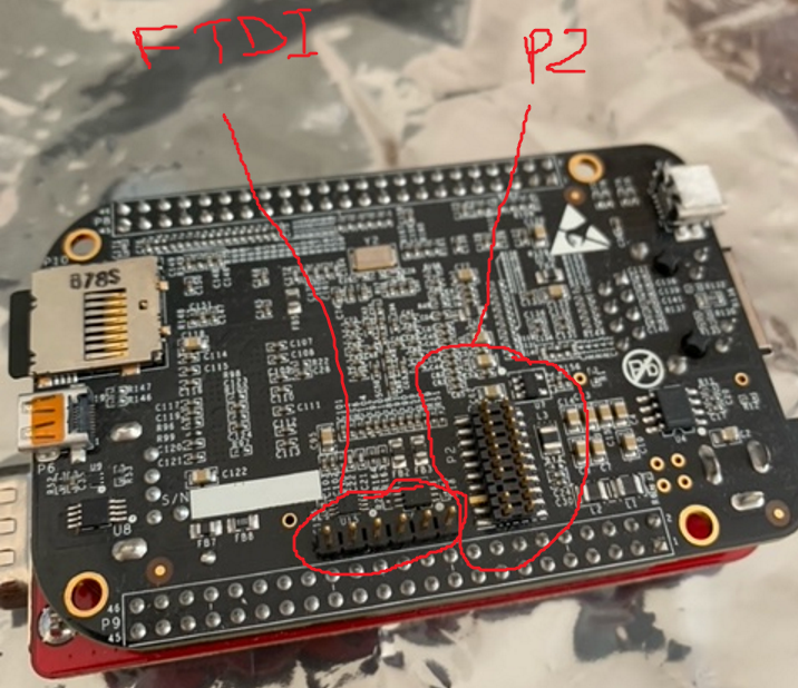
    Here's a picture of my PRU beaglebone Black setup. I populated the P2 pads - that is where the JTAG connector goes. Note that I left one pin unpopulated. I think the FTDI header sticks out of the other side of the board by default. Since I just leave the PRU Cape installed on the board, I moved the FTDI header to the same side as the P2 pads to help with Linux debug.

    I'll take a look at any responses you provide next week.

    Regards,

    Nick

  • I would not expect the board to make noises. Why are you connecting the USB to the MSP432 board?

  • Lol. Yes, I thought that was very weird too.  Good to know that I am NOT supposed to attach both USB's. I'm not sure why I thought that and I won't do it now.

    Were you able to verify my board to board connections as correct or not from my last post?

    (I updated the image in that post using the "insert/edit media" button method as you suggested).

  • Additionally, I changed my connection for J101_12 (XDSET_RESET_OUT) to go to P2.2 (TRSTn) instead of P2.15 (SRST) and now I can get into debugging window after also switching my target configuration from XDS110 USB Debug Probe to use XDS100v2 or XDS100v3 instead.

    My error seems similar but now only occurs after clicking on the target and connect target.  Here is the new error code:

    Error connecting to the target:
    (Error -151 @ 0x0)
    One of the FTDI driver functions used during the connect
    returned bad status or an error. The cause may be one or
    more of: no XDS100 is plugged in, invalid XDS100 serial number,
    blank XDS100 EEPROM, missing FTDI drivers, faulty USB cable.
    Use the xds100serial command-line utility in the 'common/uscif'
    folder to verify the XDS100 can be located.
    (Emulation package 9.2.0.00002)

    Also noteworthy, your tutorial says to hold the boot button with no SD Card in place to keep the kernel from loading but is the expectation to always have to wipe clear the entire eMMC before doing a debug session? Is there a way to not overwrite the eMMC when doing this, or am I perhaps misunderstanding something here?

  • Hello John,

    I suspect we are overthinking this. XDS110 standalone debuggers have a CTI 20 pin connection, so you can literally just install the header on Beaglebone P2 and plug the ribbon cable between the Beaglebone Black and the debugger. No manual signal selection is required.

    I am not familiar with the launchpads, so let me reassign this to our Code Composer Studio team. They can comment on whether all of the XDS110 debuggers listed in Which XDS110 is Right for Me can be used to debug other boards. If the launchpad can be used to debug BeagleBone Black, they can provide guidance on how to do it.

    Holding the boot button does not erase EMMC. Instead, it changes the boot sequence so that EMMC is not checked for boot media. If you want, you could also just erase part or all of the EMMC so that when the ROM checks EMMC for boot media, it does not find any files. See my reply to post Powering up issues for more details.

    Regards,

    Nick

  • The MSP432 LaunchPad has an XDS110 on it.  You need to have the XDS110 selected in your debug configuration and not an XDS100.

    Section 2.3.4 of the LaunchPad users guide has some information on using it to debug another board.  Note that this was designed to support debugging a custom board with a MSP432 or similar Cortex M on it and not a Cortex A based AM335x.

    https://www.ti.com/lit/ug/slau597f/slau597f.pdf?ts=1606920500034

    The LaunchPad uses a 10pin connector for external debug and the BeagleBone black uses the cTI20 header so you would additionally need an adapter.  Honestly it would be faster and cheaper just to buy a standalone XDS110.

    Regards,

    John

  • Thank you for the reply, so basically it sounds like the TDSEMU110-U (one of the less expensive debug probes I've seen so far) would be a sufficient debugger for this and the launchpad's XDS100 probably would not be sufficient?

  • John,

    Yes I would go with the TMDSEMU110-U.  The MSP432 LaunchPad does have a 110 variant on it (not a 100)  but it is stripped down a bit and would be a pain to get going with the AM335x.  There are standalone XDS100s available as well.  They are a bit cheaper but the performance is worse than the 110.  Thus the standalone 110 is the way to go.

    Regards,

    John

  • The launchpad has a 10-pin header though and the beagle has 20-pin, if I am not mistaken that would mean I would still need to make sure my connections were correct, unless there is a standard connector made for this that I am unaware of?

  • John,

    I am not aware of a standard connector that would work.  If you purchase the standalone XDS110 TMDSEMU110-U it has a cTI20 cable that you can connect to the BeagleBone black.

    Regards,

    John

  • OK. We are ordering a TMDSEMU110-U and going that direction.  Thank you, Nick and John for all the help.

  • Hopefully it isn't too late to get a reply since I already marked this as resolved, but I received my XDS110 debug probe today and just got to set it up.  And...not quite working still.  Below is the error I run into when testing connection (same as when I "connect target" as well as a picture with my setup.

    [Start: Texas Instruments XDS110 USB Debug Probe_0]

    Execute the command:

    %ccs_base%/common/uscif/dbgjtag -f %boarddatafile% -rv -o -S integrity

    [Result]


    -----[Print the board config pathname(s)]------------------------------------

    C:\Users\JMORRI~1\AppData\Local\TEXASI~1\
    CCS\ccs1011\0\0\BrdDat\testBoard.dat

    -----[Print the reset-command software log-file]-----------------------------

    This utility has selected a 100- or 510-class product.
    This utility will load the adapter 'jioxds110.dll'.
    The library build date was 'May 7 2020'.
    The library build time was '21:10:18'.
    The library package version is '9.2.0.00002'.
    The library component version is '35.35.0.0'.
    The controller does not use a programmable FPGA.

    An error occurred while hard opening the controller.

    -----[An error has occurred and this utility has aborted]--------------------

    This error is generated by TI's USCIF driver or utilities.

    The value is '-267' (0xfffffef5).
    The title is 'SC_ERR_XDS110_TARGET_SUPPLY'.

    The explanation is:
    The controller could not detect valid target supply. Check target
    JTAG connection and/or connection setting specifying voltage level.

    [End: Texas Instruments XDS110 USB Debug Probe_0]

  • Good to see the XDS110 arrived.  

    How is power being supplied to the BeagleBone black?   I can't see from the picture. Is there a 5V power supply connected or the USB cable?  The XDS110 is reporting that it does not detect power on the target.

    Regards,

    John

  • via USB. And there's a circuit of inductors/capacitors that gets hot when I connect the debugger.  Also, it seems like power turns off when I connect the debugger.

  • Running a couple quick tests...

    Test 1: Connecting USB power with debugger (holding down S2 to prevent kernel loading).  If I power the Beagle with USB before connecting debugger, the power good LED comes on and stays on until I plug in the debugger at which point, the LED turns off.  If I plug in the debugger before connecting the USB power, the power good LED flashes once and goes off immediately upon plugging in the USB.  No hot/warm circuits during this process.

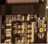
    Test 2: Power by 5v barrel jack(also holding S2).  Plugged in 5v barrel jack before debugger. Power good light came on, all circuits were normal temperature. Plugged in debugger, power good light still on, but the circuit area (picture below) next to the P2 JTAG connector got very hot very fast. Too hot to touch.  Same error -267 when I try to connect to target.  Same results when I repeat the process with debugger already plugged in prior to plugging in the 5v jack.


  • I think I am going to need to loop Nick back in.  That JTAG connector getting hot is concerning.  

    John

  • Hello John,

    We do not expect the behavior you are describing (parts of the board heating up when the debugger is connected, the board shutting off, etc). I suspect either that the board got damaged at some point during the course of this thread, or that something is not getting connected properly.

    1) Could you please upload a detailed image of the P2 header you attached? I want the picture focused enough that we can see there aren't any unwanted solder bridges, etc.

    2) Did you make any board modifications with all the experiments trying to get the MSP430 to work?

    Regards,

    Nick

  • For future readers, here are some helpful threads if you are running into JTAG issues around "The controller could not detect valid target supply.":

    JTAG connection error with BeagleBone Black
    In particular, look at the links in Pavel's first reply

    Interfacing xds110 with beaglebone black using code composer studio
    General process for interfacing CCS/XDS110/BeagleBone Black