This thread has been locked.

If you have a related question, please click the "Ask a related question" button in the top right corner. The newly created question will be automatically linked to this question.

AM4372: TPS65218D0 connection

Guru 10225 points

Part Number: AM4372
Other Parts Discussed in Thread: TPS65218D0, TMDXSK437X, TPS65216

Hi Sitara Support Team,

Regarding the combination of TPS65218D0 and AM4372, I would like to know the following questions.

1. In order to make the power supply sequence compatible with the PMIC (TPS65218D0),
 I understand that the RTC power supply is required.
 In this case, I am considering the following changes to the pins, but are there any problems with the connections?
 I'm referring to "RTC Timer Functionality but no RTC-only Mode" for the connection of each pin.

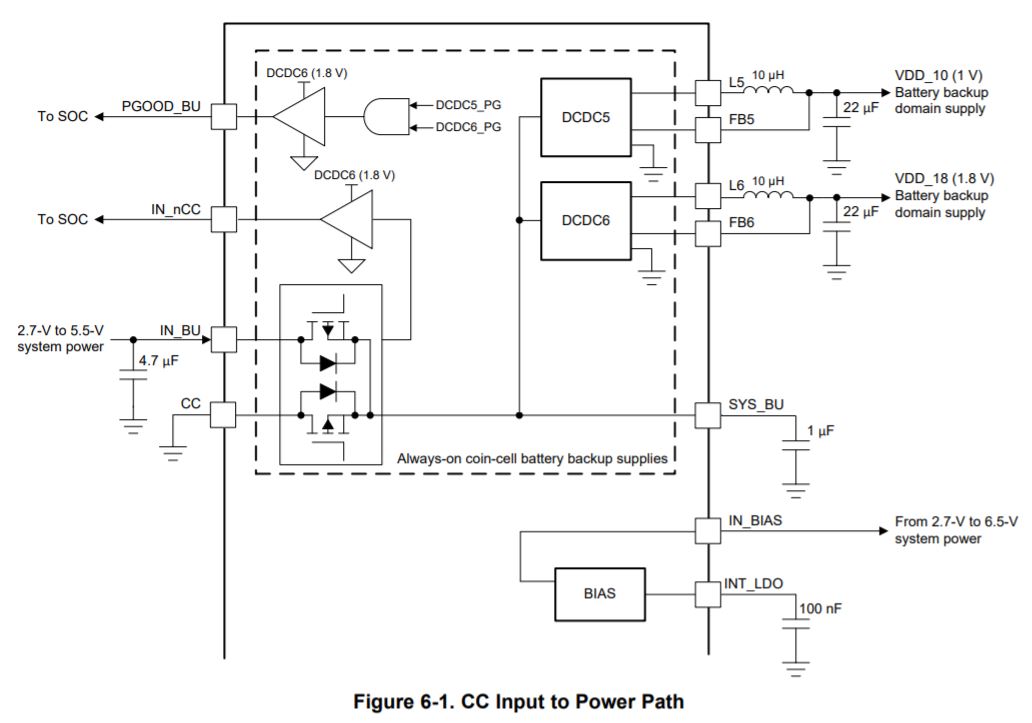
-VDDS_RTC → Change the power source from LDO1 to DCDC6.
-Connect RTC_PWRONRSTn to PGOOD_BU (TPS65218D0).
-Pull up nWAKEUP to DCDC6 with 100kΩ. 


2. Do I need an inductor or other circuit for the output?
Or is it OK to use 10kΩ pull-down as it is now?

Or does CDCD5 need to be connected to CAP_VDD_RTC as described in the user guide?
www.ti.com/.../slvuaa9b.pdf

When using the combination of TPS65218D0 and AM4372
The CAP_VDD_RTC terminal operates as an input to the RTC core voltage domain
when the internal RTC LDO is disabled by connecting the RTC.

The user guide says to connect DCDC5 and CAP_VDD_RTC.
www.ti.com/.../slvuaa9b.pdf

In AM437xSchematic Checklist, when using "RTC Timer Functionality but no RTC-only mode",
VDD_CORE and CAP_VDD_RTC should be connected.
www.ti.com/.../sprace0a.pdf

When using the combination of TPS65218D0 and AM4372,
is it possible to use it with "RTC Timer Functionality but no RTC-only mode"?

From the following post, I thought it is possible to select
"RTC Timer Functionality but no RTC-only Mode" using TPS65218D0, is this correct?

e2e.ti.com/.../416908

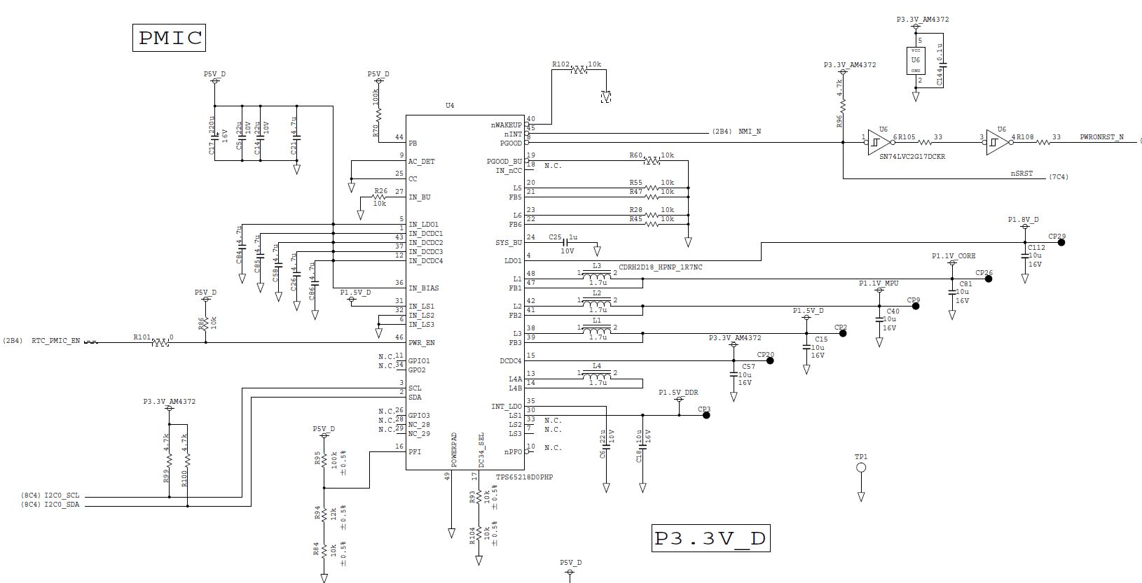
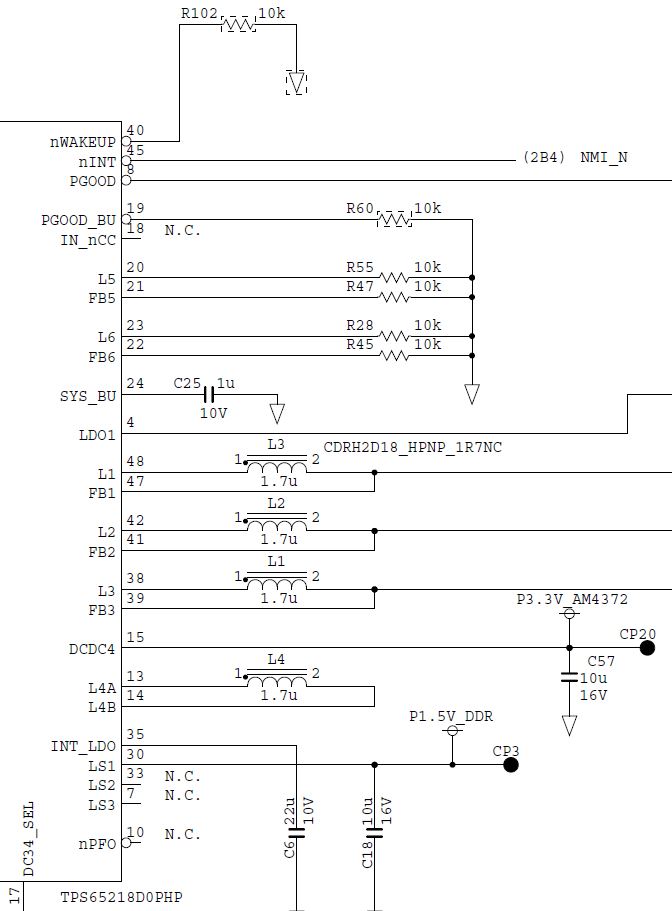
3. In addition, I am referring to the circuit diagram of the evaluation kit (StarterKitEVM437x)
 when I am unclear about the connection.

 Which use case in Table 2-3 of "Checklist" does the RTC setting of the evaluation kit correspond to?
 Was the evaluation kit designed with "RTC Timer Functionality but no RTC-only Mode" in mind?


-AM437x schematic checklist


-StarterKitEVM437x

Best regards,
Kanae

  • Hi Sitara support Team,

    Can someone please help me with this?
    Or should I post this in the Power management forum?

    If you can respond in this forum, I would appreciate it if you could let me know
    when you plan to respond as I need to report this to my customer.

    Best regards,
    Kanae

  • I need some time to review your questions. I will try to reply by mid next week.

    Regards,
    Paul

  • Hi Paul,

    Thanks for your reply.

    I will share this information with my customers.
    It would also be helpful if you could let us know
    if there is any change in your reply schedule.

    Best regards,
    Kanae

  • Yes it is possible to use the RTC functionality without using RTC-only mode, as described in the schematic checklist.


    If your customer plans to use the RTC functionality without using RTC-only mode, they can disable the internal LDO that powers RTC core logic by connecting RTC_KALDO_ENn to the same power source as VDDS_RTC, then connect VDDS_RTC to any AM437x 1.8V supply and connect CAP_VDD_RTC to the same power source as VDD_CORE. This should eliminate any concern with power sequencing since all 1.8V rails should be ramped to a valid level before the 1.1V core rail ramps.


    The RTC_PWRONRSTn can be sourced from the same reset source used for PWRONRSTn. However, RTC_PWRONRSTn doesn’t support 3.3V signal levels. So a level-shifter may be required to shift the signal down to 1.8V if PWRONRSTn is operating at 3.3V.


    The starter kit is connected as described in RTC-only mode of Table 2-3 found in the schematic checklist.


    I suggest you check with the PMIC team for their recommendation on how to tie-off wakeup or any other unused PMIC pins.


    Regards,

    Paul

  • Hi Paul,

    Thank you for your support.

    Please let me confirm about your reply,
    "connect VDDS_RTC to any AM437x 1.8V supply and connect CAP_VDD_RTC to the same power source as VDD_CORE."

    I know that the 1.8V used in AM437x is the power supply generated by LDO1 of TPS65218D0.
    In TPS65218D0 Datasheet: Applications Without Backup Battery, Figure 6-1 CC Input to Power Path,
    I think the power supply by DCDC5 and DCDC6 will be unnecessary,
    but am I right in thinking that the power circuit by DCDC5 and DCDC6 is still necessary for the power sequence?

    Also, are there any points to keep in mind when disabling the RTC function?

    Best regards,
    Kanae


  • Hi Paul,

    Thank you for your support.

    Is it better to post the additional questions on the Power Management forum
    to get a faster answer?
    I am looking forward to your advice to avoid a double thread.

    Best regards,
    Kanae

  • Sorry for the delayed reply. I got caught up working on another task and didn't see your last questions.

    You will need to ask someone from the power management team to address your questions related to unused PMIC functions.

    I was under the impression you were planning to use the real-time clock function of the RTC, but were not planning to use it while the other SOC functions were powered off (RTC-only mode), where it could be configured to wake-up the processor periodically.  So I'm not sure what you are asking with your question related to disabling the RTC function.

    I will warn you that I'm not familiar with the various software configurations supported by our software support packages. I may be able to answer very specific questions about how the RTC works or the function of a register, but will not be able to help with software configuration questions. If you need this type of help, please tell me which software package you are using and I will try to find the correct person and assign this thread to them.

    Regards,
    Paul 

  • Hi Paul,

    Thank you for your reply.

    Paul: 
    <I was under the impression you were planning to use the real-time clock function of the RTC, but were not planning to use it while the other SOC functions were powered off (RTC-only mode), where it could be configured to wake-up the processor periodically.  So I'm not sure what you are asking with your question related to disabling the RTC function.>

    I would like to respond to your comment above.

    I was aware that the RTC cannot be disabled because it uses TPS65218D0,
    so I selected "RTC Timer Functionality but no RTC-only mode" on the assumption
    that it cannot be disabled, which led to the above question.

    If it is possible to disable the RTC even using the TPS65218D0,
    please let me know how to connect it.

    The customer's requirements are as follows

    -TPS65218D0 is used
    -RTC is not required
    -S/W: iTRON

    I appreciate  to your help in finding the right person and assigning this thread.

    Best regards,
    Kanae

  • The TRM clearly defines AM437x connection expectations when the RTC is not used.  See the comment below which was copied from the TRM.

    If your application never uses the RTC functionality, connect RTC_KALDO_ENn to VDDS_RTC, CAP_VDD_RTC to VDD_CORE, and RTC_PWRONRSTn to ground. These connections disable the internal RTC LDO because RTC_KALDO_ENn is high, and they use the external VDD_CORE supply to power the RTC digital core. The RTC LDO must be disabled for internal power sequencing even though the RTC is not used. Grounding the reset signal will ensure the RTC stays in reset. Disabling the internal LDO will allow the application to achieve lower power consumption in all the low power modes.

    Does this answer your question with respect to AM4372 connectivity requirements?

    I'm not sure what "iTRON" means. I was expecting you to say Linux or RTOS. As mentioned before, I 'm not familiar with the various software offerings. Is this a software package support by TI?  If not, I'm not sure where you get support.

    Regards,
    Paul

  • Hi Paul,

    Thank you for your quick reply.
    I understood that the information in TRM is consistent with the RTC disable mode in Checklist.

    Please let me go back to my post at the beginning of this thread and ask the question again.

    Kanae:
    <1. I understand that the RTC power supply is needed to make the power supply sequence
    compatible with the PMIC (TPS65218D0). >

    Q1: Am I correct in understanding that the above is not correct,
    and that the TRM information for not using the RTC is "when using the TPS65218D0",
    and that the RTC disable mode in the Checklist can also be selected?

    Q2: The customer's system that he is considering now does not need the RTC function,
     but in order to make the power supply sequence compatible with the PMIC (TPS65218D0).
     So, he assumed that the RTC disable mode cannot be selected.
     In that case, he was considering changing the connection of the following pins
     by referring to "RTC Timer Functionality but no RTC-only Mode"
    Is it necessary to change this?

    -VDDS_RTC: Change the power supply from LDO1 to DCDC6.
    -RTC_PWRONRSTn: Connect to PGOOD_BU (TPS65218D0).
    -Pull up nWAKEUP to DCDC6 with 100kΩ.

    "Current schematic around the PMIC"

    Q3. If the change in Q2 is not necessary and there is no problem to select RTC Disable mode using TPS65218D0,
     should the customer's schematic be modified as follows?

    -RTC_KALDO_Enn: Any AM437x 1.8 V power supply -> VDDS_RTC
    -PMIC_POWER_EN : RTC_PMIC_EN → NC

    Q4. do I need an inductor or some other circuit for the output?
     Or can I use a 10kΩ pulldown as I do now?


    There may be some parts that are difficult to understand due to my poor English,
    please feel free to point out any unclear points.

    For S/W, it seems to use iTRON provided by a third party based on information from TI_RTOS.
    I am aware that you cannot provide support for this.
    Please let me check only the H/W connection method this time.

    Best regards,
    Kanae

  • Q1 - I do not know what the following statement means. "I understand that the RTC power supply is needed to make the power supply sequence compatible with the PMIC"

    I'm not aware of any power sequence requirements for the PMIC.

    Yes, you should follow the connectivity recommendation provided in the TRM.

    Q2 - I'm not a PMIC expert, but fairly sure it doesn't have power sequence requirements. I suspect you customer is getting confused by how the RTC PMIC_POWER_EN output signal is used to turn on the non-RTC power rails when using the RTC to control the PMIC. Your customer will not be using the PMIC to control the non-RTC power rails, so they need to configure the PMIC to always turn on the non-RTC rails. This may be as simple as tying off the  POWER_EN input to the PMIC, but you should get the PMIC team to confirm how this should be done.. 

    The AM437x device has power sequence requirements that are defined in the datasheet. The PMIC should sequence the AM437x supplies to be compliant with these requirements.

    The PMIC is just a power source for the AM437x device. If you do not need one of the outputs, then don't use it. However, you should ask the PMIC team how to connect unused functions on the PMIC.

    Q3 - You simply connect the AM437x RTC pins as defined in the TRM when it is not used.  You need to discuss PMIC connections with the PMIC team.

    Q4 - This is another PMIC team question.

    Regards,
    Paul

  • I just realized the paragraph in the TRM that describes how to connect RTC when not used, does not include the VDDS_RTC and RTC_WAKEUP pins.

    The RTC Feature Disabled column of Table 2-3 found in the Schematic Checklist provides a more complete list of connection requirements for this use case.

    Regards,
    Paul

  • Hi Paul,

    Thank you for your reply.

    For Q1, I had referred to the following post and determined that
    RTC disable mode cannot be selected when using PMIC.

    e2e.ti.com/.../890446

    I understand that RTC disable mode can be selected from the AM4372 side.

    I will post Q2, Q3, and Q4 in the Power Management Forum.

    If the customer is using the combination of TPS65218D0 and AM437x and
    the following user's guide connection is required,
    I will inform the customer to select the RTC only mode.

    www.ti.com/.../slvuaa9b.pdf

    Best regards,
    Kanae

  • I sent Ahmad an email asking what he meant in his reply to the E2E post you referenced. I will let you know as soon as I hear from him.

  • He said there was no significant advantage for disabling the RTC.  So he sent this reply trying to encourage customers to keep the RTC enabled since some of them were being confused by what needs to be done to disable the RTC.  It was simpler to leave it enabled.

    He also pointed be to another PMIC document which shows the TPS65216 being used to power AM437x. 

    http://www.ti.com/lit/pdf/spruip2

    Regards,
    Paul

  • Hi Paul.

    Thank you for your reply.

    I will check with the customer if it is possible to accept the configuration
    in the user guide (RTC only mode in the checklist).

    I appreciate your kind support.

    Best regards,
    Kanae