This thread has been locked.

If you have a related question, please click the "Ask a related question" button in the top right corner. The newly created question will be automatically linked to this question.

TDA4VM: Perspective Transformation in live camera feed

Part Number: TDA4VM


Hello Friends,

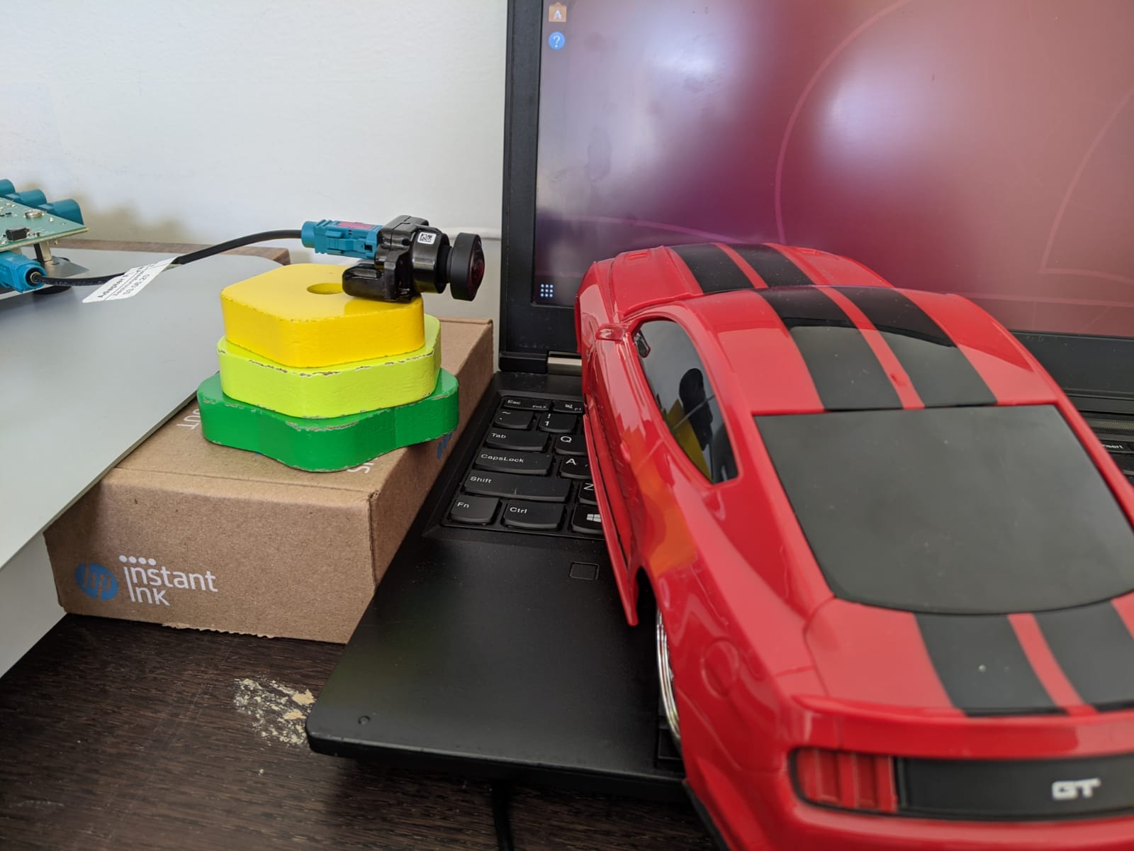
    I am trying to get Perpsective Tranformation(Bird's Eye view) of a live camera feed.I am using Sony IMX 390 Camera and I have obtained the Instrinsic Parameter details from the SDK.I have created a homography matrix.The following is the homography matrix:

vx_float32 mat[3][3] = {
                            {1.000000, -0.000000, 0.000000},                // 'x' coefficients
                           {1.582299,  0.741702, 0.001648},                // 'y' coefficients
                            {-2953.695801, -1121.453979, -2.076767}   // 'offsets'
                          };

I have modified the Single Camera App to view the Bird's eye view.I have passed the homography matrix to the WarpPerspective Node and I was able to save a Bird's eye view and view it.I was not able to view a live transformed view though.When I passed the homography matric to LDC Node or WarpPerspectieNode,I wasn't to observe any change in the output of the display which is a live camera feed.But the saved images showed the Perspective Transformation when I used WarpPerspective Node.I could not view the changes in the saved image while using LDC.I believe LDC node and Warp Perspective Node should work the same way when we give the homograpy matrix.I require your assistance to do the Perspective Transformation on a live camera feed either through WarpPerspective Node or LDC Node.(I prefer LDC Node as WarpPerspective can handle only grayscale).

Please let me know if you need further information from my side.

Thanking you in advance,

Best Regards,

Vijay

  • Can you please describe the steps followed to convert 3x3 Homography to LDC node?

  • Hello Mayank,

         I followed the steps given in the document attached.The formula used to calculate the homography matrix is K*R*Kinv where K is the camera intrinsic matrix and R is the rotational matrix.

    Best Regards,

    Vijay

     openvx_programming_guide_chapter_6.pdf

  • Hi Vijay,

    For the camera app, the transform in LDC node must be configured in "imaging/sensor_drv/src/imx390/dcc_xmls/wdr/IMX390_ldc.xml" by modifying the lines below.

    4096 // LDC_AB A(15:0) Affine Transform warp, A S16Q12
    0    // LDC_AB B(31:16) Affine Transform warp, B S16Q12
    0    // LDC_CD C(15:0) Affine Transform warp, C S16Q3
    0    // LDC_CD D(31:16) Affine Transform warp, D S16Q12
    4096 // LDC_EF E(15:0) Affine Transform warp, E S16Q12
    0    // LDC_EF F(31:16) Affine Transform warp, F S16Q3
    0    // LDC_GH G(15:0) Affine Transform warp, G S16Q23
    0    // LDC_GH H(31:16) Affine Transform warp, H S16Q23

    These are in LDC H/W integer format for normalized 3x3 homography matrix and the image pixel coordinates starts from (h=0, v=0) to (h=1919, v=1079) for IMX390.

        A, B, C,
        D, E, F,
        G, H, one,

    The values currently in xml file are for no perspective transform (identity transform with 1.0-->4096).

    You will need to convert your floating point matrix to the LDC integer format and fill them in the xml file.
    I am not familiar with the "x", "y", "offsets" notation.
    Please convert them to normalized 3x3 homogrphy first for image pixel coordinates shown above and convert the floating point numbers to integers.

    A, B, D, E are S16Q12 (i.e., floating point x 4096)

    C, F are S16Q3 (i.e., floating point x 8)

    G, H are S16Q23 (i.e., floating point x 2^23)

    Then, (1) run the "generate_dcc.sh" script in the same folder, (2) recompile imaging, (3) recompile camera app.

    Please note that the integer format is limited in precision and some floating point transforms may be possible for LDC.

  • Hello Gang,

        I was able to view the live feed on the display with the transformation.But there are a few abberations in the output.

    I have hereby given the camera placement and the corresponding output on display.

    Input 1:

    Output 1:

    Input 2:

    Output 2:

    Input 3:

    Output 3:

    We could see from the above camera placements that the transformation is performed only if the object(toy car) is at a short distance from the camera.

    We observed that with the WarpPerspective,the transformations were happening even at a large distance.Have we missed something in the process of creating the dcc_xml file.

    Please find the values given below:

                4096     // LDC_AB             A(15:0)              Affine Transform warp, A S16Q12

                  0     // LDC_AB                B(31:16)             Affine Transform warp, B S16Q12

                  0     // LDC_CD                C(15:0)              Affine Transform warp, C S16Q3

                  6481  // LDC_CD             D(31:16)             Affine Transform warp, D S16Q12

                  3038  // LDC_EF             E(15:0)              Affine Transform warp, E S16Q12

                  0     // LDC_EF             F(31:16)             Affine Transform warp, F S16Q3

                 -24777396226 // LDC_GH      G(15:0)              Affine Transform warp, G S16Q23

                 -9407437820 // LDC_GH       H(31:16)             Affine Transform warp, H S16Q23

    Best Regards,

    Vijay

  • Hi Vijay,

    I see both D and F are 0 (these are offsets in Q3).

    Most likely, your matrix values are not correct.

    Please note in my above post that the LDC H/W matrix is a mapping from integer coordinates to integer coordinates.
    The LDC Hz and Vt coordinates start from 0 and therefore image center is not (0,0), but (1920/2, 1080/2) for IMX390 input image of size 1920x1080.
    You may need to add a step for converting from your coordinates to the integer coordinates first.

    You may try a simple horizontal flip in your transform notation and translate it to LDC format.

    The correct LDC H/W matrix for horizontal flipping is

    A = -4096

    C = 1919*8

    E = 4096

    B = D = F = G = H = 0

    Best,

    Gang

  • Hi Vijay,

    Are you able to get the conversion correctly?

  • Hello Gang,

       We applied the values for horizontal flip to the dcc xml file and compiled and generated the binaries and tested.We did not get a horizontal flip in the display.The normal view was observed in the display.Please let me know if I have missed anything.

    Best Regards,

    Vijay

  • Vijay,

    Can you upload your modified "imaging/sensor_drv/src/imx390/dcc_xmls/wdr/IMX390_ldc.html" xml file?

    Are there any error messages when running "./generate_dcc.sh" for IMX390 wdr mode?
    Also, try "make imaging_srub" before "make sdk" after "./generate_dcc.sh".

    Best,

    Gang

    imaging/sensor_drv/src/imx390/dcc_xmls/wdr

  • <?xml version="1.0" encoding="utf-8"?>
    <cfg_ldc_xml xmlns:xsi="http://www.w3.org/2001/xmlschema-instance" xmlns:xsd="http://www.w3.org/2001/xmlschema">
      <!--this is a comment-->
        <dcc_name>cfg_ldc</dcc_name>
        <dcc_header>
    		<camera_module_id>    390 </camera_module_id>
    	    <dcc_descriptor_id>     5 </dcc_descriptor_id>
    	    <algorithm_vendor_id>  1 </algorithm_vendor_id>
    	    <tunning_tool_version> 0 </tunning_tool_version>
        </dcc_header>
    <!--=======================================================================-->
        <typedef>
      	<cfg_ldc_vars type="struct">
            <ldc_en type="uint16"> </ldc_en>
            <ldc_ldmapen type="uint16"> </ldc_ldmapen>
            <ldc_datamode type="uint16"> </ldc_datamode>
            <ldc_opdatamode type="uint16"> </ldc_opdatamode>
            <ldc_ip_dfmt type="uint16"> </ldc_ip_dfmt>
            <ldc_pwarpen type="uint16"> </ldc_pwarpen>
            <ldc_yint_typ type="uint16"> </ldc_yint_typ>
            <ldc_regmode_en type="uint16"> </ldc_regmode_en>
            <ldc_meshtable_m type="uint16"> </ldc_meshtable_m>
            <ldc_mesh_frsz_w type="uint16"> </ldc_mesh_frsz_w>
            <ldc_mesh_frsz_h type="uint16"> </ldc_mesh_frsz_h>
            <ldc_compute_frsz_w type="uint16"> </ldc_compute_frsz_w>
            <ldc_compute_frsz_h type="uint16"> </ldc_compute_frsz_h>
            <ldc_initx type="uint16"> </ldc_initx>
            <ldc_inity type="uint16"> </ldc_inity>
            <ldc_input_frsz_w type="uint16"> </ldc_input_frsz_w>
            <ldc_input_frsz_h type="uint16"> </ldc_input_frsz_h>
            <ldc_obw type="uint16"> </ldc_obw>
            <ldc_obh type="uint16"> </ldc_obh>
            <ldc_pixpad type="uint16"> </ldc_pixpad>
            <ldc_a type="int16"> </ldc_a>
            <ldc_b type="int16"> </ldc_b>
            <ldc_c type="int16"> </ldc_c>
            <ldc_d type="int16"> </ldc_d>
            <ldc_e type="int16"> </ldc_e>
            <ldc_f type="int16"> </ldc_f>
            <ldc_g type="int16"> </ldc_g>
            <ldc_h type="int16"> </ldc_h>
            <ldc_sf_width type="uint16[3]"> </ldc_sf_width>
            <ldc_sf_height type="uint16[3]"> </ldc_sf_height>
            <ldc_sf_en  type="uint16[3][3]"> </ldc_sf_en>
            <ldc_sf_obw type="uint16[3][3]"> </ldc_sf_obw>
            <ldc_sf_obh type="uint16[3][3]"> </ldc_sf_obh>
            <ldc_sf_pad type="uint16[3][3]"> </ldc_sf_pad>
            <ldc_ylut_en type="uint16"> </ldc_ylut_en>
            <ldc_yin_bitdpth type="uint16"> </ldc_yin_bitdpth>
            <ldc_yout_bitdpth type="uint16"> </ldc_yout_bitdpth>
            <ldc_clut_en type="uint16"> </ldc_clut_en>
            <ldc_cin_bitdpth type="uint16"> </ldc_cin_bitdpth>
            <ldc_cout_bitdpth type="uint16"> </ldc_cout_bitdpth>
            <ldc_y_lut type="uint16[513]"> </ldc_y_lut>
            <ldc_c_lut type="uint16[513]"> </ldc_c_lut>
    		<mesh_table_pitch_in_bytes type="uint32"> </mesh_table_pitch_in_bytes>
    		<mesh_table_size type="uint32"> </mesh_table_size>
    		<mesh_lut type="uint16*"> </mesh_lut>
        </cfg_ldc_vars>
        </typedef>
    <!--=======================================================================-->
    	<use_case val="1023">
            <n-space>
          <region0 class="0">
            <exposure val="1" min="0" max="2000000">  </exposure>
            <gain val="0" min="0" max="100000">  </gain>
          </region0>
        </n-space>
            <parameter_package>
                <ldc_dcc type="cfg_ldc_vars">
                {
                  1     // LDC_CTRL              LDC_EN(0)            LDC Enable, 0: Disable,  1: Enable
                  1     // LDC_CTRL              LDMAPEN(1)           LD Mapping enable, 0: disable, 1: enable
                  2     // LDC_CTRL              DATAMODE(4:3)        Input data mode, 0: YUV422,  1: Y only, 2: YUV420, 3: YUV420 UV
                  1     // LDC_CTRL              OP_DATAMODE          Output data mode, 0: keep UYVY; 1: convert to 420
                  0     // LDC_CTRL              IP_DFMT(6:5)         Input pixel format, 0: 8b,  1: 12b packed, 2: 12b unpacked
                  1     // LDC_CTRL              PWARPEN(7)           0: Disable perspective warp. 1: Enable perspective warp
                  1     // LDC_CFG               YINT_TYP(6)          Interpolation type for Y data.  0: Bicubic,  1: Bilinear
                  0     // LDC_CFG               REGMODE_EN           Region mode, 0: disable, 1: enable
                  3     // LDC_MESHTABLE_CFG     M(2:0)               Mesh table subsampling factor (0-7)
                  1920  // LDC_MESH_FRSZ       W(13:0)              Mesh frame width (0-8192)
                  1080  // LDC_MESH_FRSZ       H(29:16)             Mesh frame height (0-8192)
                  960   // LDC_COMPUTE_FRSZ      W(13:0)              Compute width (0-8192)
                  640   // LDC_COMPUTE_FRSZ      H(29:16)             Compute height (0-8192)
                    0     // LDC_INITXY            INITX(13:0)          Output starting horizontal coordinate (0-8192)
                    0     // LDC_INITXY            INITY(29:16)         Output starting vertical coordinate (0-8192)
                  1920  // LDC_INPUT_FRSZ        W(29:16)             Input frame width
                  1080  // LDC_INPUT_FRSZ        H(13:0)              Input frame height
                  128    // LDC_BLOCK_SIZE        OBW(7:0)             Output block width (0-255)
                  64    // LDC_BLOCK_SIZE        OBH(15:8)            Output block height (0-255)
                  1     // LDC_BLOCK_SIZE        PIXPAD(19:16)        Pixel pad (0-15)
                  -4096  // LDC_AB               A(15:0)              Affine Transform warp, A S16Q12
                  0     // LDC_AB                B(31:16)             Affine Transform warp, B S16Q12
                  15352 // LDC_CD                C(15:0)              Affine Transform warp, C S16Q3
                  0     // LDC_CD                D(31:16)             Affine Transform warp, D S16Q12
                  4096  // LDC_EF                E(15:0)              Affine Transform warp, E S16Q12
                  0     // LDC_EF                F(31:16)             Affine Transform warp, F S16Q3
                  0     // LDC_GH                G(15:0)              Affine Transform warp, G S16Q23
                  0     // LDC_GH                H(31:16)             Affine Transform warp, H S16Q23
                  {0, 0, 0}                             //ldc_sf_width [3]
                  {0, 0, 0}                             //ldc_sf_height[3]
                  {{0, 0, 0}, {0, 0, 0}, {0, 0, 0}}     //ldc_sf_en [3][3]
                  {{0, 0, 0}, {0, 0, 0}, {0, 0, 0}}     //ldc_sf_obw[3][3]
                  {{0, 0, 0}, {0, 0, 0}, {0, 0, 0}}     //ldc_sf_obh[3][3]
                  {{0, 0, 0}, {0, 0, 0}, {0, 0, 0}}     //ldc_sf_pad[3][3]
                  0     // LDC_DUALOUT_CFG       YLUT_EN              Luma LUT enable (0-1)
                  8     // LDC_DUALOUT_CFG       YIN_BITDPTH          Luma input bit depth (8-12)
                  8     // LDC_DUALOUT_CFG       YOUT_BITDPTH         Luma output bit depth (8-12)
                  0     // LDC_DUALOUT_CFG       CLUT_EN              Chroma LUT enable (0-1)
                  8     // LDC_DUALOUT_CFG       CIN_BITDPTH          Chroma input bit depth (8-12)
                  8     // LDC_DUALOUT_CFG       COUT_BITDPTH         Chroma output bit depth (8-12)
                  {0,0,0,0,0,0,0,0,0,0,0,0,0,0,0,0,0,0,0,0,0,0,0,0,0,0,0,0,0,0,0,0,0,0,0,0,0,0,0,0,0,0,0,0,0,0,0,0,0,0,0,0,0,0,0,0,0,0,0,0,0,0,0,0,0,0,0,0,0,0,0,0,0,0,0,0,0,0,0,0,0,0,0,0,0,0,0,0,0,0,0,0,0,0,0,0,0,0,0,0,0,0,0,0,0,0,0,0,0,0,0,0,0,0,0,0,0,0,0,0,0,0,0,0,0,0,0,0,0,0,0,0,0,0,0,0,0,0,0,0,0,0,0,0,0,0,0,0,0,0,0,0,0,0,0,0,0,0,0,0,0,0,0,0,0,0,0,0,0,0,0,0,0,0,0,0,0,0,0,0,0,0,0,0,0,0,0,0,0,0,0,0,0,0,0,0,0,0,0,0,0,0,0,0,0,0,0,0,0,0,0,0,0,0,0,0,0,0,0,0,0,0,0,0,0,0,0,0,0,0,0,0,0,0,0,0,0,0,0,0,0,0,0,0,0,0,0,0,0,0,0,0,0,0,0,0,0,0,0,0,0,0,0,0,0,0,0,0,0,0,0,0,0,0,0,0,0,0,0,0,0,0,0,0,0,0,0,0,0,0,0,0,0,0,0,0,0,0,0,0,0,0,0,0,0,0,0,0,0,0,0,0,0,0,0,0,0,0,0,0,0,0,0,0,0,0,0,0,0,0,0,0,0,0,0,0,0,0,0,0,0,0,0,0,0,0,0,0,0,0,0,0,0,0,0,0,0,0,0,0,0,0,0,0,0,0,0,0,0,0,0,0,0,0,0,0,0,0,0,0,0,0,0,0,0,0,0,0,0,0,0,0,0,0,0,0,0,0,0,0,0,0,0,0,0,0,0,0,0,0,0,0,0,0,0,0,0,0,0,0,0,0,0,0,0,0,0,0,0,0,0,0,0,0,0,0,0,0,0,0,0,0,0,0,0,0,0,0,0,0,0,0,0,0,0,0,0,0,0,0,0,0,0,0,0,0,0,0,0,0,0,0,0,0,0,0,0,0,0,0,0,0,0,0,0,0,0,0,0,0,0,0,0,0,0,0,0,0,0,0,0,0,0,0,0,0,0,0,0,0,0,0,0,},
                  {0,0,0,0,0,0,0,0,0,0,0,0,0,0,0,0,0,0,0,0,0,0,0,0,0,0,0,0,0,0,0,0,0,0,0,0,0,0,0,0,0,0,0,0,0,0,0,0,0,0,0,0,0,0,0,0,0,0,0,0,0,0,0,0,0,0,0,0,0,0,0,0,0,0,0,0,0,0,0,0,0,0,0,0,0,0,0,0,0,0,0,0,0,0,0,0,0,0,0,0,0,0,0,0,0,0,0,0,0,0,0,0,0,0,0,0,0,0,0,0,0,0,0,0,0,0,0,0,0,0,0,0,0,0,0,0,0,0,0,0,0,0,0,0,0,0,0,0,0,0,0,0,0,0,0,0,0,0,0,0,0,0,0,0,0,0,0,0,0,0,0,0,0,0,0,0,0,0,0,0,0,0,0,0,0,0,0,0,0,0,0,0,0,0,0,0,0,0,0,0,0,0,0,0,0,0,0,0,0,0,0,0,0,0,0,0,0,0,0,0,0,0,0,0,0,0,0,0,0,0,0,0,0,0,0,0,0,0,0,0,0,0,0,0,0,0,0,0,0,0,0,0,0,0,0,0,0,0,0,0,0,0,0,0,0,0,0,0,0,0,0,0,0,0,0,0,0,0,0,0,0,0,0,0,0,0,0,0,0,0,0,0,0,0,0,0,0,0,0,0,0,0,0,0,0,0,0,0,0,0,0,0,0,0,0,0,0,0,0,0,0,0,0,0,0,0,0,0,0,0,0,0,0,0,0,0,0,0,0,0,0,0,0,0,0,0,0,0,0,0,0,0,0,0,0,0,0,0,0,0,0,0,0,0,0,0,0,0,0,0,0,0,0,0,0,0,0,0,0,0,0,0,0,0,0,0,0,0,0,0,0,0,0,0,0,0,0,0,0,0,0,0,0,0,0,0,0,0,0,0,0,0,0,0,0,0,0,0,0,0,0,0,0,0,0,0,0,0,0,0,0,0,0,0,0,0,0,0,0,0,0,0,0,0,0,0,0,0,0,0,0,0,0,0,0,0,0,0,0,0,0,0,0,0,0,0,0,0,0,0,0,0,0,0,0,0,0,0,0,0,0,0,0,0,0,0,0,0,0,0,0,0,0,0,0,0,0,0,0,0,0,0,0,0,0,0,0,0,0,0,0,0,0,},
                  976,
                  66368,
                  {
                      #include "ldc_xml_IMX390_1920x1080_3.txt"
                  }
                }
              </ldc_dcc>
            </parameter_package>
        </use_case>
    <!--=====================================================================-->
    </cfg_ldc_xml>
    
    Hi Gang, 

    build success (no error ). 

    Logs, 

    vadivel@vadivel-Thinkpad-P50:~/workspace/adas/ti/ti-processor-sdk-rtos-j721e-evm-07_02_00_06/imaging/sensor_drv/src/imx390/dcc_xmls/wdr$ sudo ./generate_dcc.sh
    rm: cannot remove '*.bin': No such file or directory
    Parsing: [IMX390_ipipe_rgb2rgb_1_dcc.xml] [OK!]
    Generating CRC: [18F10844] [OK!]
    Generating BIN file... [OK!]
    Parsing: [IMX390_viss_h3a_aewb_cfg.xml] [OK!]
    Generating CRC: [D0295AD2] [OK!]
    Generating BIN file... [OK!]
    Parsing: [IMX390_viss_nsf4.xml] [OK!]
    Generating CRC: [41DA95E1] [OK!]
    Generating BIN file... [OK!]
    Parsing: [IMX390_viss_ee.xml] [OK!]
    Generating CRC: [9A70A925] [OK!]
    Generating BIN file... [OK!]
    Parsing: [IMX390_viss_blc.xml] [OK!]
    Generating CRC: [3C7EA53F] [OK!]
    Generating BIN file... [OK!]
    Parsing: [IMX390_flxd_cfa.xml] [OK!]
    Generating CRC: [31358E23] [OK!]
    Generating BIN file... [OK!]
    Parsing: [IMX390_rawfe_decompand.xml] [OK!]
    Generating CRC: [DC5E70D] [OK!]
    Generating BIN file... [OK!]
    Parsing: [IMX390_viss_h3a_mux_luts_cfg.xml] [OK!]
    Generating CRC: [C5BE9ED1] [OK!]
    Generating BIN file... [OK!]
    Parsing: [IMX390_viss_glbce.xml] [OK!]
    Generating CRC: [53EFD937] [OK!]
    Generating BIN file... [OK!]
    ../../dcc_bins/dcc_viss_wdr.bin ../../../../include/dcc_viss_imx390_wdr.h dcc_viss_imx390_wdr

    Converting binary file [../../dcc_bins/dcc_viss_wdr.bin] to C array .. Do[OK!]34575 bytes)Parsing: [IMX390_awb_alg_ti3_tuning.xml]
    Generating CRC: [184E603C] [OK!]
    Generating BIN file... [OK!]
    Parsing: [IMX390_viss_h3a_aewb_cfg.xml] [OK!]
    Generating CRC: [D0295AD2] [OK!]
    Generating BIN file... [OK!]
    ../../dcc_bins/dcc_2a_wdr.bin ../../../../include/dcc_2a_imx390_wdr.h dcc_2a_imx390_wdr

    Converting binary file [../../dcc_bins/dcc_2a_wdr.bin] to C array .. Done[OK!]036 bytes)Parsing: [IMX390_ldc.xml]
    Generating CRC: [C5D5EAA1] [OK!]
    Generating BIN file... [OK!]
    ../../dcc_bins/dcc_ldc_wdr.bin ../../../../include/dcc_ldc_imx390_wdr.h dcc_ldc_imx390_wdr

    Converting binary file [../../dcc_bins/dcc_ldc_wdr.bin] to C array .. Done. (135088 bytes)vadivel@vadivel-Thinkpad-P50:~/workspace/adas/ti/ti-processor-sdk-rtos-j721e-evm-07_02_00_06/imaging/sen02_00_06/imaging90/dcc_xmls/wdr$ cd ~/workspace/adas/ti/ti-processor-sdk-rtos-j721e-evm-07_0
    vadivel@vadivel-Thinkpad-P50:~/workspace/adas/ti/ti-processor-sdk-rtos-j721e-evm-07_02_00_06/imaging$

    Regads, 

    Vadivel

  • This looks correct.

    I did the same as you and then the following steps to rebuild

    - "make imaging_scrub"

    - "make sdk"

    The output image is properly flipped on my EVM with "vx_app_single_cam".

    A minor difference is that I never used "sudo" in any steps (so not sure if it matters).

    Did you enable LDC while running "vx_app_single_cam"?

  • YES, I have enabled LDC. 

    Supported sensor list:
    a : IMX390-UB953_D3
    b : AR0233-UB953_MARS
    c : AR0820-UB953_LI
    d : UB9xxx_RAW12_TESTPATTERN
    e : UB96x_UYVY_TESTPATTERN
    f : GW_AR0233_UYVY
    Select a sensor
    [MCU2_0] 682.393410 s: ImageSensor_RemoteServiceHandler: IM_SENSOR_CMD_CREATE
    [MCU2_0] 682.393480 s: Sensor at index 0 = IMX390-UB953_D3
    [MCU2_0] 682.393512 s: Sensor at index 1 = AR0233-UB953_MARS
    [MCU2_0] 682.393539 s: Sensor at index 2 = AR0820-UB953_LI
    [MCU2_0] 682.393564 s: Sensor at index 3 = UB9xxx_RAW12_TESTPATTERN
    [MCU2_0] 682.393591 s: Sensor at index 4 = UB96x_UYVY_TESTPATTERN
    [MCU2_0] 682.393619 s: Sensor at index 5 = GW_AR0233_UYVY
    a

    LDC Selection Yes(1)/No(0)
    LDC Selection Yes(1)/No(0)
    1
    Sensor selected : IMX390-UB953_D3
    Querying IMX390-UB953_D3
    687.795150 s: ISS: Querying sensor [IMX390-UB953_D3] ... !!!
    687.795463 s: ISS: Querying sensor [IMX390-UB953_D3] ... Done !!!
    687.795474 s: ISS: Initializing sensor [IMX390-UB953_D3], doing IM_SENSOR_CMD_PWRON ... !!!
    [MCU2_0] 687.795279 s: ImageSensor_RemoteServiceHandler: IM_SENSOR_CMD_QUERY
    [MCU2_0] 687.795369 s: Received Query for IMX390-UB953_D3
    [MCU2_0] 687.795565 s: ImageSensor_RemoteServiceHandler: IM_SENSOR_CMD_PWRON
    [MCU2_0] 687.795650 s: IM_SENSOR_CMD_PWRON : channel_mask = 0x1
    [MCU2_0] 687.795707 s: IMX390_PowerOn : chMask = 0x1
    [MCU2_0] 687.795749 s: ub960_cfgScript : ub960I2cAddr = 0x3d
    [MCU2_0] 687.795776 s: UB960 config start
    687.995747 s: ISS: Initializing sensor [IMX390-UB953_D3], doing IM_SENSOR_CMD_CONFIG ... !!!
    [MCU2_0] 687.995628 s: End of UB960 config
    [MCU2_0] 687.995899 s: ImageSensor_RemoteServiceHandler: IM_SENSOR_CMD_CONFIG
    [MCU2_0] 687.995953 s: Application requested features = 0x358
    [MCU2_0]
    [MCU2_0] 687.996020 s: ub960_cfgScript : ub960I2cAddr = 0x3d
    [MCU2_0] 687.996052 s: UB960 config start
    [MCU2_0] 688.251451 s: End of UB960 config
    [MCU2_0] 688.251548 s: ub960_cfgScript : ub960I2cAddr = 0x36
    [MCU2_0] 688.251584 s: UB960 config start
    [MCU2_0] 688.507449 s: End of UB960 config
    [MCU2_0] 688.507522 s: Configuring camera # 0
    [MCU2_0] 688.507556 s: ub953 config start : slaveAddr = 0x74
    [MCU2_0] 688.697460 s: End of UB953 config
    [MCU2_0] 688.697554 s: Configuring IMX390 imager 0x40.. Please wait till it finishes
    690.775563 s: ISS: Initializing sensor [IMX390-UB953_D3] ... Done !!!
    reading test RAW image /opt/vision_apps/test_data/img_test.raw
    read_test_image_raw : Unable to open file /opt/vision_apps/test_data/img_test.raw
    Enabling LDC
    [MCU2_0] 690.775382 s: IMX390 config done
    [MCU2_0] 690.775446 s: IM_SENSOR_CMD_CONFIG returning status = 0
    Scaler is disabled


    ==========================
    Demo : Single Camera w/ 2A
    ==========================

    p: Print performance statistics

    s: Save Sensor RAW, VISS Output and H3A output images to File System

    e: Export performance statistics

    u: Update DCC from File System


    x: Exit

    Enter Choice:
    Unsupported command

    ==========================
    Demo : Single Camera w/ 2A
    ==========================

    p: Print performance statistics

    s: Save Sensor RAW, VISS Output and H3A output images to File System

    e: Export performance statistics

    u: Update DCC from File System


    x: Exit

    Enter Choice: 690.825472 s: ISS: Starting sensor [IMX390-UB953_D3] ... !!!
    [MCU2_0] 690.825679 s: ImageSensor_RemoteServiceHandler: IM_SENSOR_CMD_STREAM_ON
    [MCU2_0] 690.825752 s: IM_SENSOR_CMD_STREAM_ON: channel_mask = 0x1
    [MCU2_0] 690.825823 s: ub960_cfgScript : ub960I2cAddr = 0x3d
    [MCU2_0] 690.825856 s: UB960 config start
    [MCU2_0] 691.081447 s: End of UB960 config
    [MCU2_0] 691.081544 s: ub960_cfgScript : ub960I2cAddr = 0x36
    [MCU2_0] 691.081580 s: UB960 config start
    [MCU2_0] 691.337452 s: End of UB960 config
    [MCU2_0] 691.337512 s: Starting camera # 0
    [MCU2_0] 691.337562 s: Entering IssSensor_Start
    [MCU2_0] 691.347397 s: enableUB960Streaming ub960InstanceId = 0
    [MCU2_0] 691.347626 s: ub960_cfgScript : ub960I2cAddr = 0x3d
    [MCU2_0] 691.347659 s: UB960 config start
    691.379582 s: ISS: Starting sensor [IMX390-UB953_D3] ... !!!
    [MCU2_0] 691.379451 s: End of UB960 config
    [MCU2_0] 693.531728 s: DHCP client timed out. Retrying.....

  • Yes, 1 is for LDC enable.

    I don't see anything wrong, if you did "make imaging_scrub" before "make sdk" as well.

    Can you press "s" and upload the saved viss output and ldc output YUV images?

  • Hi Gang Hua,

    It is working as you described.  Sorry, for my incorrect observation (I have noticed that after showing some text image on camera).

    Regards, 

    Vadivel 

  • Thanks for the update.

    Now you may experiment with your matrix notation to generate a flipping matrix and convert it to LDC H/W format.

    Once you get it to work properly, you shall be able to convert your matrix above.