


Other Parts Discussed in Thread: TP120,
Hi TI,
I want to toggle GPIO1_13, which is connected to TP120 on the SOM board. To do that, I modified the led_blink example from pdk/packages/ti/drv/gpio. I am using the latest version of the pdk (pdk_jacinto_07_01_05_14). I did the following changes:
- Add Pinmux Config for GPIO1_13
/* MyGPIO1 -> GPIO1_13 -> V6 */
    {
        PIN_TIMER_IO0, PIN_MODE(7) | \
        ((PIN_PULL_DISABLE) & (~PIN_PULL_DIRECTION & ~PIN_INPUT_ENABLE))
    },
In this case, GPIO1_13 is configured as TX. But since I can change the direction of the Pin directly in the driver, the direction in the pinmux config is not important. Is this assumption correct?
- Removed second GPIO from gpioPinConfigs in gpio/test/led_blink/j721e/GPIO_board.c
/* GPIO Driver board specific pin configuration structure */
GPIO_PinConfig gpioPinConfigs[] =
{
    /* Input pin with interrupt enabled */

    /* Output pin */
    GPIO_DEVICE_CONFIG(GPIO_LED1_PORT_NUM, GPIO_LED1_PIN_NUM) |
    GPIO_CFG_OUTPUT
};
Since I only want to toggle the PIN, I did not see a reason to keep this second GPIO in the PinConfig.
- Change PIN number in gpio/test/led_blink/src/GPIO_board.h to 13
#if defined (j721e_evm) || defined (j7200_evm)
/* J7ES: use WAKEUP GPIO0_6 --> TP45 for testing */
#define GPIO_LED0_PIN_NUM        13U /* Pin 6 */
#define GPIO_LED0_PORT_NUM       0 /* use WAKEUP GPIO0 */
#define GPIO_LED1_PIN_NUM        13U /* Pin 6 */
#define GPIO_LED1_PORT_NUM       0 /* use WAKEUP GPIO0 */
#endif
Here I simply changed to PIN_NUM to the deisred one (13). LED0PIN/PORT is not used due to the previous change. PORT_NUM is also not important due to the change in the following step.
- Change baseAddr in gpio/test/led_bink/src/main_led_blink.c
#if defined(j721e_sim) || defined (j721e_evm) || defined (j7200_evm)

    /* no main domain GPIO pins directly connected to LEDs on GP EVM,
       use WKUP domain GPIO pins which connected to LEDs on base board */
    cfg->baseAddr = CSL_GPIO1_BASE ;
I changed the baseAddr to the desired one (CSL_GPIO1_BASE) and I did that on all occurencies of baseAddr.
With these changes I was now able to write to the corresponding registers:
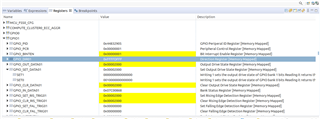
However, I still can not change the state of TP120 (verify with a scope). Can you help me to find the missing idea to get this working?
Thanks and best regards,
Felix
