This thread has been locked.

If you have a related question, please click the "Ask a related question" button in the top right corner. The newly created question will be automatically linked to this question.

AM3359: CortxA8: Error connecting to the target: (Error -2062 @ 0x1851960)

Part Number: AM3359

Hi all,

we have developed custom board with am3359 processor. we are not getting CCCC ASCII char printed  on console.

Setting SYSBOOT[5] = 1 will output the system clock on CLKOUT1 we are able to monitor the clock

using Analyzing Boot Issues with CCS and JTAG we are able to test the connection, but when trying to run the script following error is displayed

js:> loadJSFile /home/astra/Downloads/am335x-boot.dss
Error connecting to the target: emulation failure occurred (/home/astra/Downloads/am335x-boot.dss#369)

CortxA8: Error connecting to the target: (Error -2062 @ 0x1851960) Unable to halt device. Reset the device, and retry the operation. If error persists, confirm configuration, power-cycle the board, and/or try more reliable JTAG settings (e.g. lower TCLK). (Emulation package 8.0.27.9)


Thanks in advance.

  • Hi,

    You should check whether you have external 4.7kOhm pullup resistors to VDDSHV6 on the EMU0 and EMU1 pins. Also you should be aware that the "CCC..." sequence will be printed out only if you have UART0 in your SYSBOOT sequence.
  • Update: We are using USB560 v2 System Trace JTag from Blackhawk (BH-USB-560v2)
  • Hi Biser,

    Our SYSBOOT sequence is according to the Table  26-7. SYSBOOT Configuration Pins in the AM335x TRM

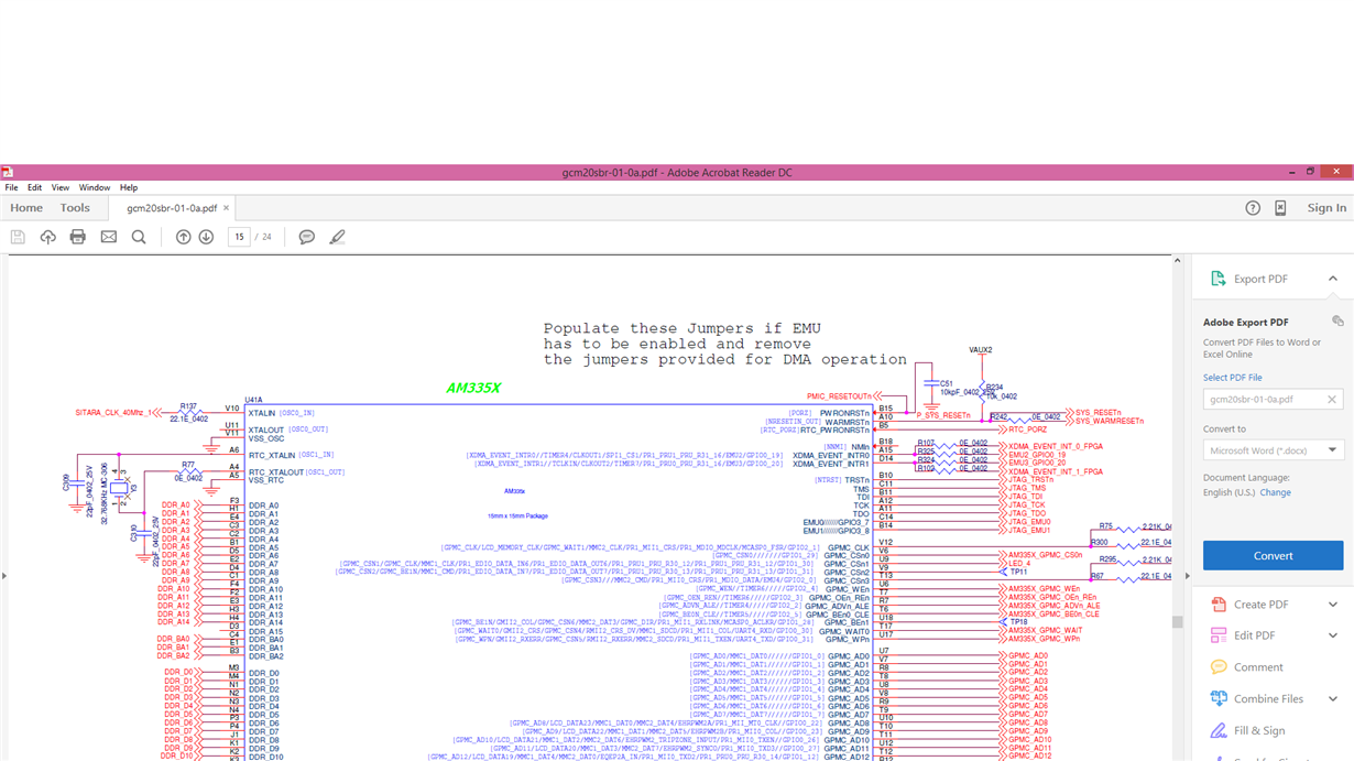
    Both EMU0 and EMU1 are pulled up using 4.7k ohm resistors.

    Thanks.

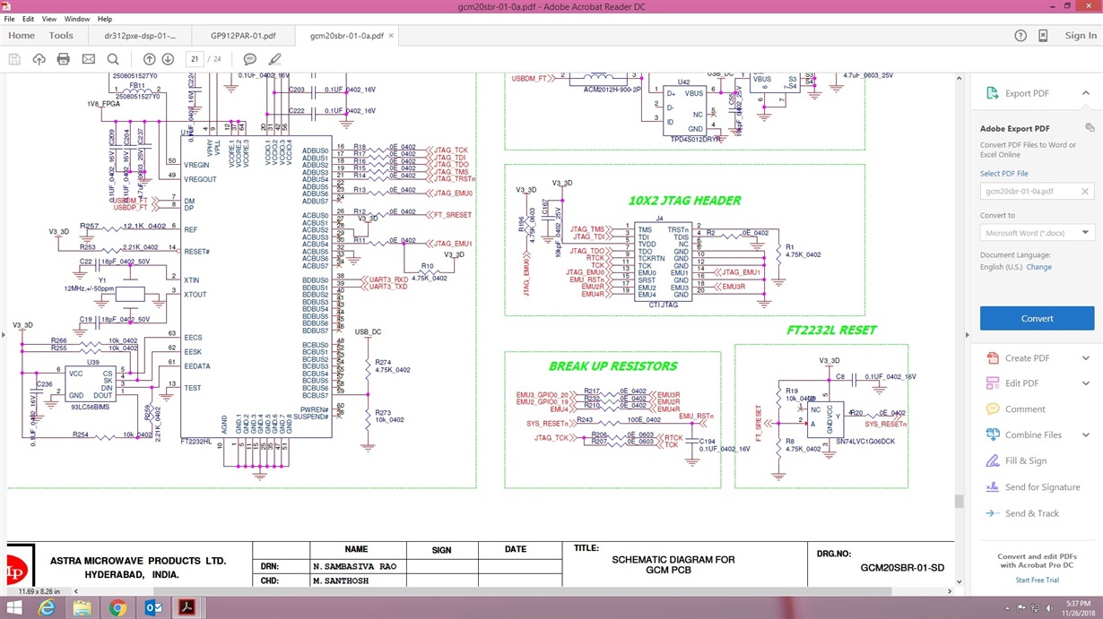
  • Please post the JTAG portion of the schematic.
  • Please also post your SYSBOOT[15:0] configuration.
  • Hi Biser,

    attaching the jtag connections we are using jtag header ftdi connections are by passed 

    SYSBOOT[15:0]  = 0x8021 (1000000000100001)

    Thank you,

    Sandeep

  • Can you also post the JTAG connections on the AM335x side? I don't see JTAG_TRSTn going anywhere.
    On the SYSBOOT settings, are you using a 25MHz crystal?
  • Please check whether JTAG_TRSTn is connected to the JTAG header. I don't see a net label on the header side.
  • S it has been connected using one more header
  • What is your main clock frequency? Please recheck the JTAG_TRSTn signal on the PCB.
  • Dear Biser,

    JTAG_TRSTn pin is connected on different header we are wiring it to JTAG
    my clock frequency is 25MHz and I can see it on CLKOUT1

    My test connection from CCS Is passing using JTAG
  • OK, that sorts out the JTAG hardware. Please describe what is this script that you try loading? Did you initialize the device beforehand?
  • Hi Biser,
    I have downloaded am335x.dss file from tips and debug and trying to run that script

    Thanks, Sandeep
  • What software is this? Linux? RTOS? Please post the link where you downloaded the file.
  • We are using Linux Ubuntu 18.04
    I have downloaded .dss file from below link
    processors.wiki.ti.com/.../AM335x_board_bringup_tips
  • Hi Sandeep,

    We are sorry about the inconvenience but our expert on the topic is not available today and we should be able to give you feedback by early next week.

    Regards,
    Krunal
  • Hi biser ,

    attaching the boot analsys report 

    CONTROL: device_id = 0x2b94402e
      * AM335x family
      * Silicon Revision 2.1
    
    PRM_DEVICE: PRM_RSTST = 0x00000221
      * Bit 0 : GLOBAL_COLD_RST
      * Bit 5 : EXTERNAL_WARM_RST
    
    CONTROL: control_status = 0x00ff03ff
      * SYSBOOT[15:14] = 11b (26 MHz)
      * SYSBOOT[13:12] have been set improperly!
      * SYSBOOT[11:10] = 11b ILLEGAL VALUE!
      * SYSBOOT[9] = 0 GPMC CS0 Ignore WAIT input
      * SYSBOOT[9] = 1 GPMC CS0 Use WAIT input
      * SYSBOOT[8] = 0 GPMC CS0 8-bit data bus
      * SYSBOOT[8] = 1 GPMC CS0 16-bit data bus
      * Device Type = General Purpose (GP)
      * SYSBOOT[7:6] = 11b RGMII no internal delay (EMAC boot modes only)
      * SYSBOOT[5] = 1 CLKOUT1 enabled
      * Boot Sequence : Fast External Boot -> EMAC1 -> UART0 -> Reserved
    
    ROM: Current tracing vector, word 1 = 0x2869a525
      * Bit 0  : [General] Passed the public reset vector
      * Bit 2  : [General] Running after the cold reset
      * Bit 5  : [Peripheral Boot] Peripheral booting started
      * Bit 8  : [Boot] Reserved
      * Bit 10 : [Peripheral Boot] Reserved
      * Bit 13 : [Peripheral Boot] ASIC ID sent
      * Bit 15 : [Peripheral Boot] Peripheral booting failed
      * Bit 16 : [Peripheral Boot] Booting Message not received (timeout)
      * Bit 19 : Reserved
      * Bit 21 : [Configuration Header] CHSETTINGS executed
      * Bit 22 : [Configuration Header] CHRAM executed
      * Bit 27 : Reserved
      * Bit 29 : Reserved
    
    ROM: Current tracing vector, word 1 = 0xb13d5de3
      * Bit 0  : [Companion chip] Reserved
      * Bit 1  : [Companion chip] Reserved
      * Bit 5  : [USB] USB configured state
      * Bit 6  : [USB] USB VBUS valid
      * Bit 7  : [USB] USB session valid
      * Bit 8  : Reserved
      * Bit 10 : Reserved
      * Bit 11 : Reserved
      * Bit 12 : [Memory Boot] Memory booting trial 0
      * Bit 14 : [Memory Boot] Memory booting trial 2
      * Bit 16 : [Memory Boot] Execute GP image
      * Bit 18 : [Memory & Peripheral Boot] Jumping to Initial SW
      * Bit 19 : [Memory & Peripheral Boot] Reserved
      * Bit 20 : [Memory & Peripheral Boot] Start image authentication
      * Bit 21 : [Memory & Peripheral Boot] Image authentication failed
      * Bit 24 : [Memory & Peripheral Boot] Reserved
      * Bit 28 : [Memory & Peripheral Boot] Authentication procedure failed
      * Bit 29 : Reserved
      * Bit 31 : Reserved
    
    ROM: Current tracing vector, word 1 = 0xe6f39a72
      * Bit 1  : [Memory Boot] Memory booting device XIP
      * Bit 4  : [Memory Boot] Reserved
      * Bit 5  : [Memory Boot] Memory booting device MMCSD0
      * Bit 6  : Reserved
      * Bit 9  : Reserved
      * Bit 11 : Reserved
      * Bit 12 : Memory booting device SPI
      * Bit 15 : Reserved
      * Bit 16 : Peripheral booting device UART0
      * Bit 17 : Reserved
      * Bit 20 : [Peripheral Boot] Peripheral booting device USB
      * Bit 21 : [Peripheral Boot] Reserved
      * Bit 22 : [Peripheral Boot] Peripheral booting device GPGMAC0
      * Bit 23 : Reserved
      * Bit 25 : Reserved
      * Bit 26 : Reserved
      * Bit 29 : Reserved
      * Bit 30 : Reserved
      * Bit 31 : Reserved
    
    ROM: Current copy of PRM_RSTST = 0xc3bb5d41
      * Bit 0 : GLOBAL_COLD_RST
    
    ROM: Cold reset tracing vector, word 1 = 0xa3619a05
      * Bit 0  : [General] Passed the public reset vector
      * Bit 2  : [General] Running after the cold reset
      * Bit 9  : [Boot] Reserved
      * Bit 11 : [Peripheral Boot] Reserved
      * Bit 12 : [Peripheral Boot] Device initialized
      * Bit 15 : [Peripheral Boot] Peripheral booting failed
      * Bit 16 : [Peripheral Boot] Booting Message not received (timeout)
      * Bit 21 : [Configuration Header] CHSETTINGS executed
      * Bit 22 : [Configuration Header] CHRAM executed
      * Bit 24 : [Configuration Header] CHMMCSD clocks executed
      * Bit 25 : [Configuration Header] CHMMCSD bus width executed
      * Bit 29 : Reserved
      * Bit 31 : Reserved
    
    ROM: Cold reset tracing vector, word 1 = 0xed086634
      * Bit 2  : [Companion chip] Reserved
      * Bit 4  : [USB] USB connect
      * Bit 5  : [USB] USB configured state
      * Bit 9  : Reserved
      * Bit 10 : Reserved
      * Bit 13 : [Memory Boot] Memory booting trial 1
      * Bit 14 : [Memory Boot] Memory booting trial 2
      * Bit 19 : [Memory & Peripheral Boot] Reserved
      * Bit 24 : [Memory & Peripheral Boot] Reserved
      * Bit 26 : [Memory & Peripheral Boot] Reserved
      * Bit 27 : [Memory & Peripheral Boot] Reserved
      * Bit 29 : Reserved
      * Bit 30 : Reserved
      * Bit 31 : Reserved
    
    ROM: Cold reset tracing vector, word 1 = 0xcde171e8
      * Bit 3  : [Memory Boot] Memory booting device NAND
      * Bit 5  : [Memory Boot] Memory booting device MMCSD0
      * Bit 6  : Reserved
      * Bit 7  : [Memory Boot] Memory booting device MMCSD1
      * Bit 8  : Reserved
      * Bit 12 : Memory booting device SPI
      * Bit 13 : Reserved
      * Bit 14 : Reserved
      * Bit 16 : Peripheral booting device UART0
      * Bit 21 : [Peripheral Boot] Reserved
      * Bit 22 : [Peripheral Boot] Peripheral booting device GPGMAC0
      * Bit 23 : Reserved
      * Bit 24 : Peripheral booting device NULL
      * Bit 26 : Reserved
      * Bit 27 : Reserved
      * Bit 30 : Reserved
      * Bit 31 : Reserved
    
    Cortex A8 Program Counter = 0x00020000
    
    ROM Exception Vectors
      * 0x4030CE04 Undefined
      * 0x4030CE08 SWI
      * 0x4030CE0C Pre-fetch abort
      * 0x4030CE10 Data abort
      * 0x4030CE14 Unused
      * 0x4030CE18 IRQ
      * 0x4030CE1C FIQ
    
    ROM Dead Loops
      * 0x00020080 Undefined exception default handler
      * 0x00020084 SWI exception default handler
      * 0x00020088 Pre-fetch abort exception default handler
      * 0x0002008C Data exception default handler
      * 0x00020090 Unused exception default handler
      * 0x00020094 IRQ exception default handler
      * 0x00020098 FIQ exception default handler
      * 0x0002009C Validation test PASS
      * 0x000200A0 Validation test FAIL
      * 0x000200A4 Reserved
      * 0x000200A8 Image not executed or returned
      * 0x000200AC Reserved
      * 0x000200B0 Reserved
      * 0x000200B4 Reserved
      * 0x000200B8 Reserved
      * 0x000200BC Reserved
    

    it shows some pins have been configured improperly though i can probe them on scope

    thank you,

    Sandeep.M

  • Part Number: AM3359

    Tool/software: Linux

    Dear TI Team,

    Please find the thread link below and help to resolve asap.

    https://e2e.ti.com/support/processors/f/791/t/750012 

    Customer is facing issue on debug AM3359 processor using usb560v2 jtag emulator (custom board). I have attached the schematic FYR. 

    Awaiting for early reply.

    Regards,

    Muthu SAstra_Microwave_gcm20sbr-01-0a.pdf

  • Hi,

    Your SYSBOOT signals are connected in parallel to the FPGA, the FTDI chip, and a temperature sensor I2C (with pullups to an entirely different power rail). You must ensure that the additional connections are not overriding the SYSBOOT settings at reset release time, which I believe is the case.