Other Parts Discussed in Thread: TLV320AIC3254
Hello,
we have the following system which works with synchronous clocks. One AIC3204 is the i2s master of the whole system and generates the clocks for all i2s slaves. Servicing of c5535 i2s is done by dma. The c5535 just loop through the audio data at the moment. The audio transfers work, but sometimes the audio is scrambled after power on. When we reinit the codec and the dsp i2s and dma, scrambling dissappears. What could be the reason for this scrambling?!
The init procedure of AIC3204 is as follows. The only difference in initialization of master or slave is the register 27 in page 0 (marked in red).
CSL_Status AIC3254_Init(Bool master)
{
CSL_Status result = CSL_SOK;
result = AIC3254_Write(0, 0); // write 0 to page register to select page 0
if (result != CSL_SOK)
{
return result;
}
result = AIC3254_Write(1, 1); // reset codec
if (result != CSL_SOK)
{
return result;
}
/* Select the PLL input and CODEC_CLKIN */
/* PLL input is assumed as 12MHz */
result = AIC3254_Write(4, 0x03);
if (result != CSL_SOK)
{
return result;
}
/*
PLL_CLK = (PLL_CLKIN * R * J.D)/P
DAC_FS = PLL_CLK/(NDAC * MDAC * DOSR)
ADC_FS = PLL_CLK/(NADC * MADC * AOSR)
DAC_CLK = PLL_CLK/NDAC
BCLK = DAC_CLK/BDIV_CLKIN
DAC_FS, BCLK:
16 kHz: P=1, R=1, J=7, D=1754 (0x6da)
NDAC=6, MDAC=7, DOSR=128
BCLK = 28
PLL_CLK = (12e6 * 1 * 7.1754)/1 = 86104800
DAC_FS = PLL_CLK/(6 * 7 * 128) = 16016.52
BCLK = PLL_CLK/NDAC/BCLK = 28701600/2/28 = 512528.57
ADC_FS:
16 kHz: P=1, R=1, J=7, D=1754 (0x6da)
NADC=6, MADC=7, AOSR=128
ADC_FS = PLL_CLK/(2 * 7 * 128) = 16016.52
*/
// Power up the PLL and set P = 1 & R = 1
result = AIC3254_Write(5, 0x91); // 16khz
if (result != CSL_SOK)
{
return result;
}
// Set J value to 7
result = AIC3254_Write(6, 0x07); // 16khz
if (result != CSL_SOK)
{
return result;
}
//
// CODEC_CLKIN = 12MHz *(R * J.D)/P
//
// Set D value(MSB) = 0x06
result = AIC3254_Write(7, 0x6); // 16khz
if (result != CSL_SOK)
{
return result;
}
// Set D value(LSB) = 0xda
result = AIC3254_Write(8, 0xda); // 16khz
if (result != CSL_SOK)
{
return result;
}
// Set NDAC to 6 - this along with BCLK N configures BCLK
result = AIC3254_Write(11, 0x86); // 16khz
if (result != CSL_SOK)
{
return result;
}
// Set MDAC to 7
result = AIC3254_Write(12, 0x87); // 16khz
if (result != CSL_SOK)
{
return result;
}
//
// DAC_FS = (12MHz *(R * J.D)/P)/(NDAC * MDAC * DOSR)
//
/* Set DAC OSR MSB value to 0 */
result = AIC3254_Write(13, 0x0);
if (result != CSL_SOK)
{
return result;
}
// Set DAC OSR LSB value to 128
// This generates the DAC_FS = 16KHz
result = AIC3254_Write(14, 128); // 16khz
if (result != CSL_SOK)
{
return result;
}
//
// BCLK = (12MHz *(R * J.D)/P)/(NDAC * BCLK N)
//
// Set BCLK N value to 28
// This along with NDAC generates the BCLK = 512 kHz
// BCLK = (12MHz *(R * J.D)/P)/(NDAC * BCLK N)
result = AIC3254_Write(30, 0x9C); // 16khz
if (result != CSL_SOK)
{
return result;
}
// Set ADC_FS to 16 kHZ
// Set NADC to 6
result = AIC3254_Write(18, 0x86); // 16khz
if (result != CSL_SOK)
{
return result;
}
// Set MADC to 7
result = AIC3254_Write(19, 0x87); // 16khz
if (result != CSL_SOK)
{
return result;
}
// Set ADC OSR LSB value to 128
// This generates the ADC_FS = 16KHz
// ADC_FS = (12MHz *(R * J.D)/P)/(NADC * MADC * AOSR)
result = AIC3254_Write(20, 128); // 16khz
if (result != CSL_SOK)
{
return result;
}
if (master == TRUE)
{
result = AIC3254_Write(27,0xd); // BCLK and WCLK is set as op to AIC3254(Master)
if (result != CSL_SOK)
{
return result;
}
}
result = AIC3254_Write(0, 1); // select page 1
if (result != CSL_SOK)
{
return result;
}
result = AIC3254_Write(51, 0x48); // power up Mic Bias using LDO-IN
if (result != CSL_SOK)
{
return result;
}
result = AIC3254_Write(1, 0x8); // Disable crude AVDD generation from DVDD
if (result != CSL_SOK)
{
return result;
}
result = AIC3254_Write(2, 1); // Enable Analog Blocks and internal LDO
if (result != CSL_SOK)
{
return result;
}
result = AIC3254_Write(20, 0); // Depop reg R=6K,t=8RC(2.256ms),ramp time=0ms
if (result != CSL_SOK)
{
return result;
}
result = AIC3254_Write(14, 0x8); // LDAC AFIR routed to LOL
if (result != CSL_SOK)
{
return result;
}
result = AIC3254_Write(15, 0x8); // RDAC AFIR routed to LOR
if (result != CSL_SOK)
{
return result;
}
result = AIC3254_Write(52, 0xC0); // Route IN1L to LEFT_P with 40K input impedance
if (result != CSL_SOK)
{
return result;
}
result = AIC3254_Write(54, 0xC0); // Route Common Mode to LEFT_M with impedance of 40K
if (result != CSL_SOK)
{
return result;
}
result = AIC3254_Write(55, 0xC0); // Route IN1R to RIGHT_P with 40K input impedance
if (result != CSL_SOK)
{
return result;
}
result = AIC3254_Write(57, 0xC0); // Route Common Mode to RIGHT_M with impedance of 40K
if (result != CSL_SOK)
{
return result;
}
result = AIC3254_Write(59, 0x00); // Unmute Left MICPGA, Gain = 0 dB
if (result != CSL_SOK)
{
return result;
}
result = AIC3254_Write(60, 0x00); // Unmute Right MICPGA, Gain = 0 dB
if (result != CSL_SOK)
{
return result;
}
result = AIC3254_Write(0, 0); // write 0 to page register to select page 0
if (result != CSL_SOK)
{
return result;
}
result = AIC3254_Write(86, 0x90); // Enable LEFT AGC, target level -8dBFs
if (result != CSL_SOK)
{
return result;
}
result = AIC3254_Write(94, 0x90); // Enable RIGHT AGC, target level -8dBFs
if (result != CSL_SOK)
{
return result;
}
result = AIC3254_Write(64, 0x2); // DAC left vol=right vol
if (result != CSL_SOK)
{
return result;
}
result = AIC3254_Write(63, 0xd4); // DAC power up left, right data paths and set channel
if (result != CSL_SOK)
{
return result;
}
result = AIC3254_Write(64, 0xc); // DAC mute
if (result != CSL_SOK)
{
return result;
}
result = AIC3254_Write(0, 1); // select page 1
if (result != CSL_SOK)
{
return result;
}
result = AIC3254_Write(18, 0); // unmute LOL, 0dB gain
if (result != CSL_SOK)
{
return result;
}
result = AIC3254_Write(19, 0); // unmute LOR, 0dB gain
if (result != CSL_SOK)
{
return result;
}
result = AIC3254_Write(9, 0x0C); // power up LOL, LOR
if (result != CSL_SOK)
{
return result;
}
result = AIC3254_Write(0, 0x0); // select page 0
if (result != CSL_SOK)
{
return result;
}
result = AIC3254_Write(64, 0x2); // unmute DAC with right vol=left vol
if (result != CSL_SOK)
{
return result;
}
result = AIC3254_Write(65, 0); // set DAC gain to 0dB
if (result != CSL_SOK)
{
return result;
}
result = AIC3254_Write(66, 0); // set DAC gain to 0dB
if (result != CSL_SOK)
{
return result;
}
result = AIC3254_Write(81, 0xc0); // Powerup left and right ADC
if (result != CSL_SOK)
{
return result;
}
result = AIC3254_Write(82, 0x00); // Unmute left and right ADC
if (result != CSL_SOK)
{
return result;
}
result = AIC3254_Write(83, 0); // Set left ADC Gain to 0dB
if (result != CSL_SOK)
{
return result;
}
result = AIC3254_Write(84, 0); // Set right ADC Gain to 0dB
if (result != CSL_SOK)
{
return result;
}
return result;
}
Initialization of C5535 i2s is as follows:
CSL_Status I2sInit(void)
{
CSL_Status status;
I2S_Config hwConfig;
hI2sLoc->configured = false;
/* Set the value for the configure structure */
hwConfig.dataFormat = I2S_DATAFORMAT_LJUST;
hwConfig.dataType = I2S_STEREO_ENABLE;
hwConfig.loopBackMode = I2S_LOOPBACK_DISABLE;
hwConfig.fsPol = I2S_FSPOL_LOW; // I2S_FSPOL_HIGH
hwConfig.clkPol = I2S_RISING_EDGE; // I2S_FALLING_EDGE
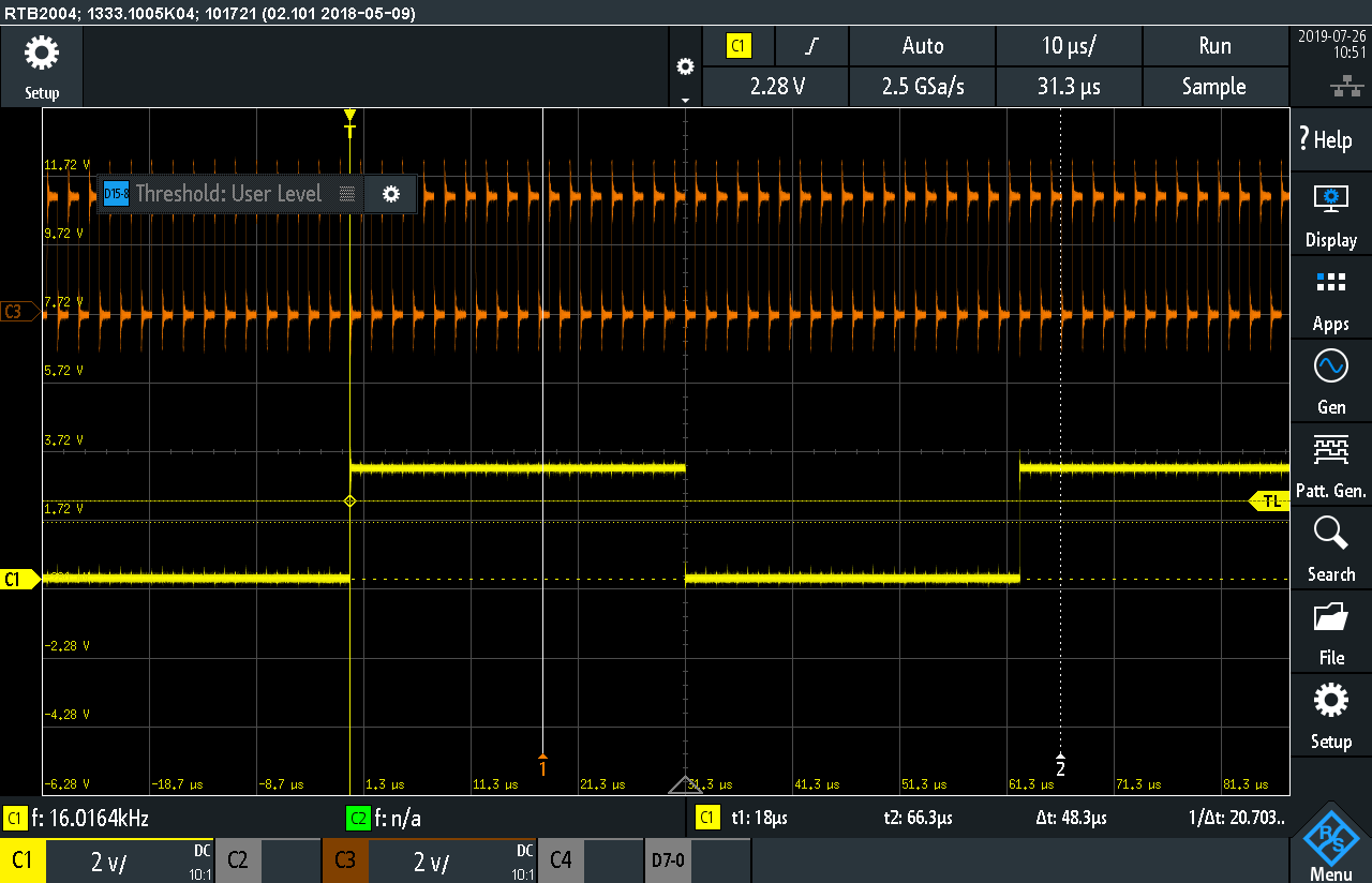
hwConfig.datadelay = I2S_DATADELAY_ONEBIT;
hwConfig.datapack = I2S_DATAPACK_ENABLE;
hwConfig.signext = I2S_SIGNEXT_DISABLE;
hwConfig.wordLen = I2S_WORDLEN_16;
hwConfig.i2sMode = I2S_SLAVE;
hwConfig.clkDiv = I2S_CLKDIV2; // don't care for slave mode
hwConfig.fsDiv = I2S_FSDIV32; // don't care for slave mode
hwConfig.FError = I2S_FSERROR_DISABLE;
hwConfig.OuError = I2S_OUERROR_DISABLE;
/* Configure hardware registers */
status = I2S_setup(hI2sLoc, &hwConfig);
if (status != CSL_SOK)
{
printf("Setup I2S Loc Module failed\n");
return (status);
}
hI2sRem->configured = false;
/* Set the value for the configure structure */
hwConfig.dataFormat = I2S_DATAFORMAT_LJUST;
hwConfig.dataType = I2S_STEREO_ENABLE;
hwConfig.loopBackMode = I2S_LOOPBACK_DISABLE;
hwConfig.fsPol = I2S_FSPOL_LOW; // I2S_FSPOL_HIGH
hwConfig.clkPol = I2S_RISING_EDGE; // I2S_FALLING_EDGE
hwConfig.datadelay = I2S_DATADELAY_ONEBIT;
hwConfig.datapack = I2S_DATAPACK_ENABLE;
hwConfig.signext = I2S_SIGNEXT_DISABLE;
hwConfig.wordLen = I2S_WORDLEN_16;
hwConfig.i2sMode = I2S_SLAVE;
hwConfig.clkDiv = I2S_CLKDIV2; // don't care for slave mode
hwConfig.fsDiv = I2S_FSDIV32; // don't care for slave mode
hwConfig.FError = I2S_FSERROR_DISABLE;
hwConfig.OuError = I2S_OUERROR_DISABLE;
/* Configure hardware registers */
status = I2S_setup(hI2sRem, &hwConfig);
if (status != CSL_SOK)
{
printf("Setup I2S Rem failed\n");
return (status);
}
return CSL_SOK;
}
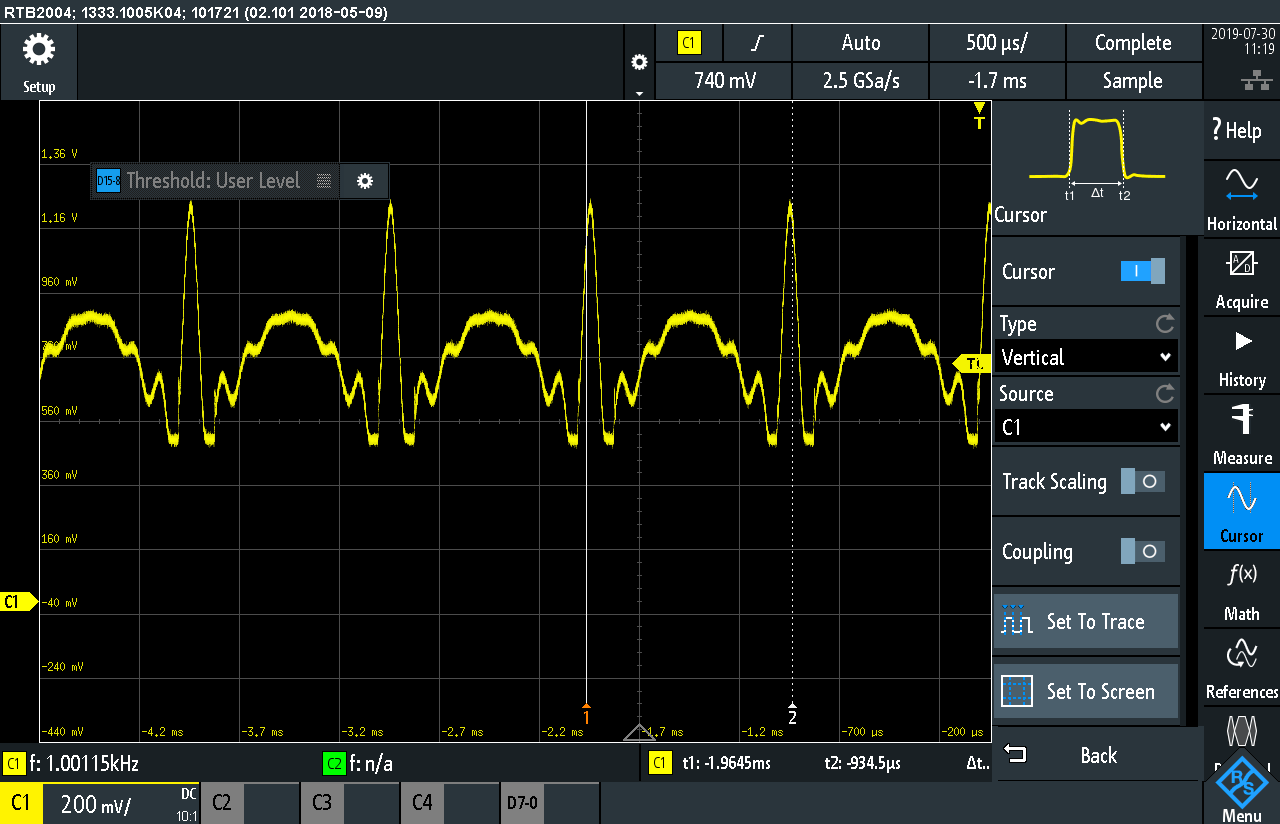
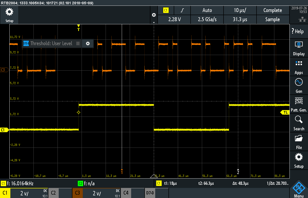
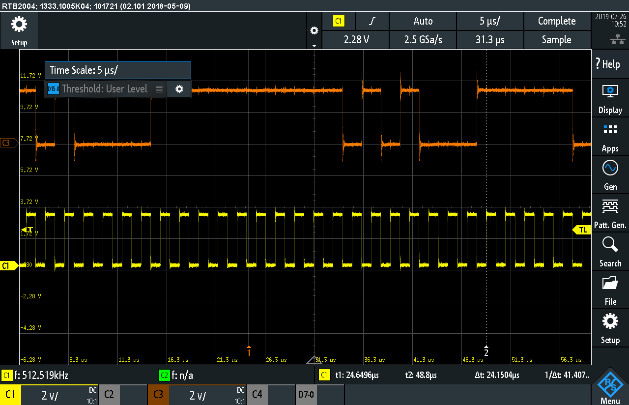
I2s WCLK and BCLK look as follows:
The peaks at the BCLK occur due to not connected ground on oscilloscope.
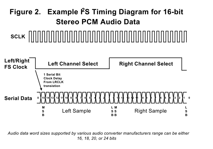
I2s WCLK and Data:
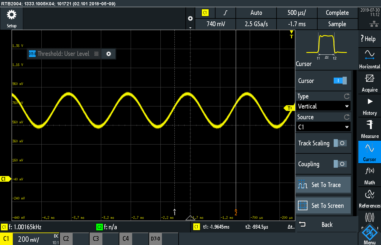
I2s BCLK and Data:
We don't know if the initialization of the aic3204 and c5535 i2s is correct and match each other. We took them out of example code from ti (Beam form application and C55x USB Audio Class Framework). It would be fine if you could take a look at the init procedures and the screenshots. Perhaps you can see the reason for the scrambled sound?! As already mentioned, scrambling only appears sporadic after init of codec and c5535 i2s. When we do a reinit, it dissappears.
Is the data delay of one bit correct? In my understanding this means that the data is valid after the second rising edge on BCLK after WCLK change.But then only 15 rising BCLK edges remain?!?! What about the c5535 Frame Clock Timing Requirement in Slave Mode mentioned in chapter 2.4 in http://www.ti.com/lit/ug/sprufp4a/sprufp4a.pdf?? It is mentioned that the WCLK can be delayed by a RC combination. But why is the RC placed at the DOUT pin and not at the WCLK pin in Figure 6??
Thanks in advance and have a nice day
Marc