This thread has been locked.

If you have a related question, please click the "Ask a related question" button in the top right corner. The newly created question will be automatically linked to this question.

AFE7950: The bandwidth signal amplitude of AFE7950

Part Number: AFE7950


Hi,

        We purchased AFE7950EVM and tested it together with ZCU102.  I have applied for TI's JESD204B IP.

        I use this source code package: ZCU102-AFE79xx_8b10b10Gbps.  According to document TI204c-Setup.docx,I connected TXA to a spectrograph and measured a single tone signal with an amplitude of around -9.5dbm.

      I generated a linear frequency modulation signal with a bandwidth of 100MHz using Matlab, with 1024 sampling points and a sampling rate of 491.52MHz.

      I modified the FPGA code of zcu102 and modified the ‘refdesign_tx.sv’ file to enable the FPGA to transmit 1024 point IQ signals.

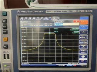
      But when I measured the signal amplitude of txA on the spectrograph, it was only -23.2dbm. Is this amplitude normal and can it still be increased?


  • Hi,

     I need to add some information. I hope to receive your reply as soon as possible.

    This is my AFE configuration:

    sysParams.FadcFb = 2949.12

    sysParams.Fdac = 2949.12*4 = 11796.48

    sysParams.ddcFactorRx = [6]*4 # DDC

    sysParams.ducFactorTx = [24]*4 #DUC

    sysParams.LMFSHdTx = ["44210","44210","44210","44210"]

    sysParams.LMFSHdRx = ["44210","44210","44210","44210"]

    sysParams.txNco0 = [[9500,9500], [9500,9500], [9500,9500], [9500,9500]] 

    sysParams.rxNco0 = [[9500,9500], [9500,9500], [9500,9500], [9500,9500]] 

    Matlab script:

    B=100e6;
    fs=491.52e6;
    N=1024;
    n=16;
    %%
    T=N/fs;%         
    K=B/T;%调频率
    t=linspace(-T/2,T/2,N);
    
    y = exp( 1i  * pi * K * t.^2) * (2^(n-1));
    datI = round(real(y));
    datQ = round(imag(y));
    

    FPGA Code  to transmit IQ signals:

    reg [7:0] sine_count;
    
    always @(posedge tx_sys_clock or negedge master_reset_n)
    begin
    	if (!master_reset_n)
    	 sine_count <= 8'd0;
    	else
    	 if (tx_lane_data_ready)
    	  sine_count <= sine_count + 1;
    end
    
    assign tx_lane_data[0][63 -: 16] = sine_i[0][1023 - sine_count*4];
    assign tx_lane_data[0][47 -: 16] = sine_i[0][1022 - sine_count*4];
    assign tx_lane_data[0][31 -: 16] = sine_i[0][1021 - sine_count*4];
    assign tx_lane_data[0][15 -: 16] = sine_i[0][1020 - sine_count*4];
    
    assign tx_lane_data[1][63 -: 16] = sine_q[0][1023 - sine_count*4];
    assign tx_lane_data[1][47 -: 16] = sine_q[0][1022 - sine_count*4];
    assign tx_lane_data[1][31 -: 16] = sine_q[0][1021 - sine_count*4];
    assign tx_lane_data[1][15 -: 16] = sine_q[0][1020 - sine_count*4];

    Please help me confirm if the IQ signal I generated using Matlab signal is correct?  Is there an error in FPGA code transmission of 1024 IQ points?

    We hope the signal amplitude can be increased to around -10dbm.

  • Hi TI Team,

           May I ask if there is any progress on my question?

  • Hi Xiao,

    With a single tone signal, output power is concentrated at one frequency. So, output power can be measured by placing a marker at the tone frequency. But, with a wide-band signal, output power is spread over a frequency band. Output power should be measured in a channel power measurement mode of spectrum analyzer. 

    To verify the output power from AFE's DAC, you can try with a single tone first before trying custom signals. 

    Regards,

    Vijay

  • Hi Vijayendra Varma Siddamsetty,

             From the demo code you provided, I know that by replacing the “samples_vector” array with sine signals of other frequencies, the “NCO+sine freq” signal can be generated. But this is only limited to sine frequencies that are multiples of 7.68 MHz.

           So if the frequency of the sine waveform is 10MHz and the sample point number is not an integer multiple of 16, how can it match with the data width of tx_lane_data?