This thread has been locked.

If you have a related question, please click the "Ask a related question" button in the top right corner. The newly created question will be automatically linked to this question.

LMP91300: Communication protocol of the LMP91300SWIFEVM

Part Number: LMP91300
Other Parts Discussed in Thread: SN74AHC1G04, INA270

Hi,                                                                                                                                                        

I would like to know if there is any way to verify that the LMP91300SWIFEVM communicates correctly with LMP91300NPN.

It uses the SWIF protocol (Content 7.5.2), but I can not see variation in the power supply, neither writing or reading (Content 7.5.2.1 and 7.5.2.2).

I try to follow point 8.2.2.2 to correctly calibrate the Rp of the LC Tank, but I do not see variation in the INA / INB terminals when modifying the values of the registers.

I also do not understand, that if I write values in some registers using the GUI, when I read it, I do not get the values that iI write, the registers values changes, usually 0xff.

I have connected everything according to the LMP91300SWIFEVM User's Guide (2.3.Settings).

It is necessary to connect and feed the development board according to point 2.2. (Input/Output Connector Description)?

For these reasons, I understand that the LMP91300SWIFEVM board does not communicate correctly with the LMP91300NPN.

May you help us?

Thanks,

Guillermo Peña

  • Hello,
    We received your request. Please allow us some time to look into the matter. In the meantime if you could share with us the sensor characteristics you have connected? If there is no signal on the INA/INB terminals then I would suspect that the sensor is either not inside the design space or potentially damaged. I would also confirm that there are no shorts from soldering or incorrect components on the board. Have you built up more than one unit to verify that it's not something wrong with this specific board?
    Thanks!
    Luke
  • Hello,
    Additionally, could you check the voltage between pin 13 and pin 6 using a floating DMM? It should be 8V. If there's any type of protection circuitry it will cause a voltage drop that is seen between pins 13 and 6. For example the SWIF board will be putting out 8V, but the voltage between pins 13 and 6 could be 6.5V because of resistors and diodes. In this case the LMP91300 will not recognize the SWIF communication. Once you verify that the 8V supply is set correctly, the 12V supply can be set by stacking 4V on top of the 8V supply.

    Another possibility is if the registers were burned in the part at some point, which depending on what version of the burn was done it could have disabled SWIF.
    Regards,
    Luke
  • Hi,

    -We are using a square coil (15.5x15.5mm). There are signal on the INA/NB terminals, I can see with a osciloscope how varies the signal approaching a metal object.

    -Yes, we have built up more tan one unit, it happends the same in all of the units.

    -The voltage between pin 13 and pin 6 is set correctly, it is more or less 8V, 7.6V exactly.

    It is probable that the problem is in the LMP91300SWIFEVM, when I use the GUI, read / write command, I do not see any variation in the SWIF_MISO / MOSI test points, I only see a 7.8V continuous signal.

    We have not burned any registers yet. How many times can the LMP91300 be burned?

    Thanks!

  • Hello,
    Thanks for the confirmation on the voltage levels and the sensor signal.
    It sounds like there may be a problem on the SWIF board and not necessarily the LMP board. I would first confirm that the MSP has been flashed properly. Can you confirm which file you used to flash the device? Also can you let us know what it shows up as in device manager? If it is being recognized properly, then I would check to see if it is damaged in any way. You could try to probe the SWIF signal out of the MSP directly and make sure you see the appropriate signals. This will help us narrow it down to see if it's the firmware or if the driving circuitry is damaged.
    Thanks!
    Luke
  • Hello,

    I use the data file lmp91300_rv_strm.txt to flash the device. In the device manager, it show me that the tipe of device is NSC_USB_WV5 and the name of the device is TI,MSP430, I understand that it is recognized properly.
    If I probe the SWIF signal out of the MSP directly, I can see the pwm signal, but the higher output level is 1.92V, it seems to me that the U10(EL7156) always put 8V on the output because always see a low level.

    There are the same voltaje levels at the input and output of the U13(SN74AHC1G04).

    What do you think? It could be about the firmware?

    Thanks

  • Hello,

    Thanks for the confirmation about the firmware. It sounds like this is most likely not the issue.

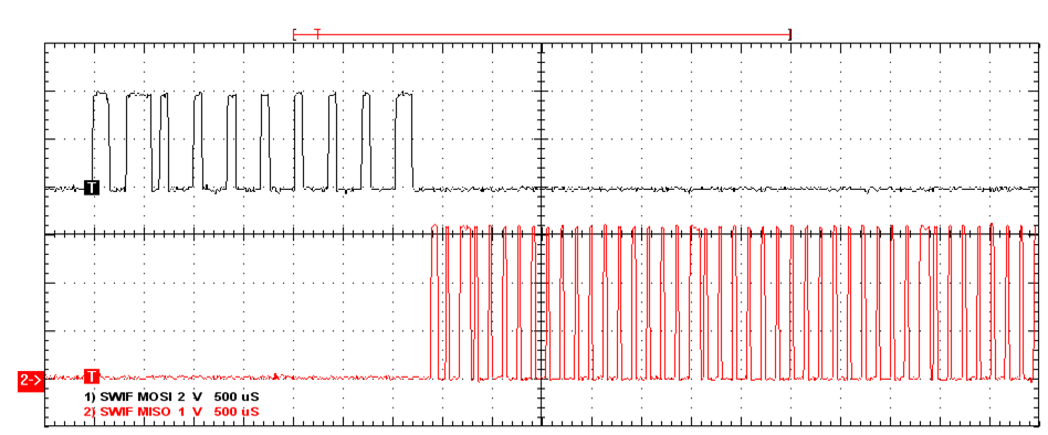
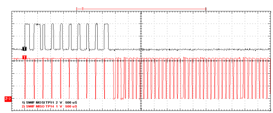
    Is it still possible to clarify if you have 8V and 12V at the pins of the part? The signals should look like these below.

    Thanks!

    Luke

  • Hi,

    Sorry for answering so late.

    Currently the system works as shown in those images, we had a problem with U13(SN74AHC1G04) and with U7(MSP430), changing those components has been the solution.

    Thanks for helping

    Best regards.

  • Hello,
    Thanks for the update! I will go ahead and close this thread.
    Thanks,
    Luke
  • Hi Luke,

    We have found some problems with the recepcion of the SWIF MISO protocol. We use the LMP91300_NPN. For this example, I try to read the register 0x6a.

    In the next picture you can see the registers configurations:

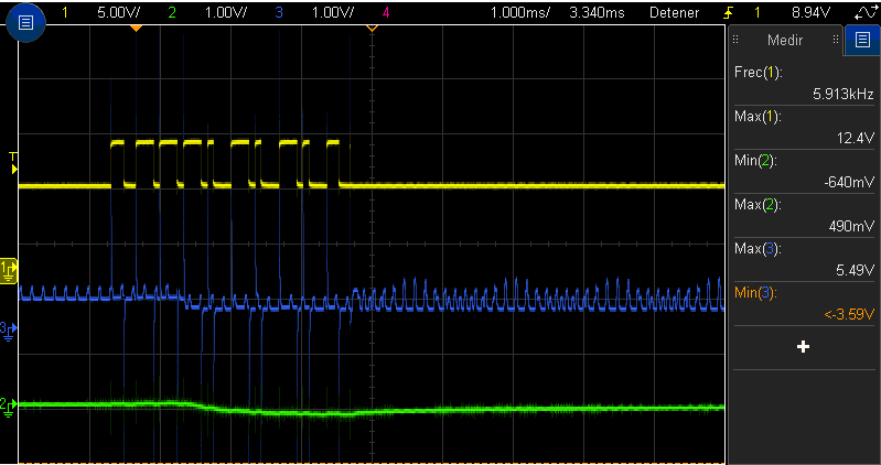
    The signals look like below:

    The yelow signal: TP11

    The blue signal: J3, positive point, it goes to pin 8 of INA270.

    The green signal: TP12 (SWIF MISO)

    As you can see, the miso signal is not correct. What do you think?

    Thanks!

    Regards.

  • Adjusting of the capacitor in the terminals CFA and CFB, the ripple disappears in the blue signal of the first picture.

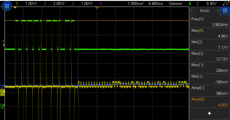
    I want to update the signals picture:

    The green signal: TP11

    The yelow signal: J3, positive point, it goes to pin 8 of INA270.

    The blue signal: TP12 (SWIF MISO)

    The amplitude of the yelow signal is 720mV. Could this be the reason why the INA270 does not work properly?

    Thanks.

    Regards.

  • Hello,

    Have you tried probing the pins of INA270? Specifically, what's the supply voltage and the output? Doing so can help us narrow down the problem.

    Thanks,
    Jiashow
  • Hello,

    Thanks for your response. This is the schematic that we are using, without mounting D1, D6, R23 and U13, the supply voltage is 12V, and C11 is 0.1uF.

    This is the register configuration:

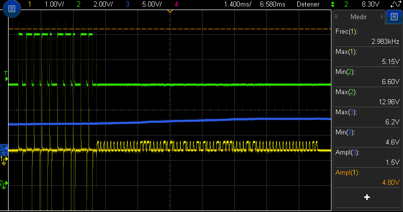
    We are trying to read the register 6D as you can see in the green signal. The yellow signal is the reply of the LMP, measured in the pin 8 of the INA270. The blue signal is the output of the INA270.
    The output voltage is always about 4.6V, growing up to 6.2 V when we read a register. After read, it becomes down to 4.6 V.

    Thanks. 

  • Hello,

    This sounds like a problem with INA270. Let me forward this post to the current sensing forum.

    Best,
    Jiashow
  • As you say, it was a problem with the INA270. I wanted to be carefully before change it.

    Thank you.

    Regards.

  • Hello everyone,

    User5223880, I assume you want TP12 (or INA270 output to look like a switching digital signal similar to the yellow signal (differential input of INA270 switching around 8kHz)?

    Why did you populate C11 with 0.1uF? This creates a 16.58Hz low-pass filter inside the INA270. This seems like it would remove the switching and turn the INA270 output into a DC signal.

    Best regards,
    Peter Iliya
    Current Sensing Applications
  • Hello User5223880,

    I have not heard back from you. If you have more questions do not hesistate to post back.

    Sincerely,
    Peter Iliya