This thread has been locked.

If you have a related question, please click the "Ask a related question" button in the top right corner. The newly created question will be automatically linked to this question.

AWR1243: AWR1243

Part Number: AWR1243

Hi,

I am still struggling to exchange messages with my evaluation board AWR1243BOOST using an external host processor based on FPGA. At this time I can reliably get out of boot up async event and can get the response with MSS start up time. I attempt to request data from the device using a command word found on the forum https://e2e.ti.com/support/sensors-group/sensors/f/sensors-forum/720669/awr1243boost-awr1243-crc-calculation but i am not sure if it is compatible with new version of the board/firmware. Could you provide me with a simple message waiting for response (with irq turned high by slave) and the expected response? My board is revision B. Versions are:

BSSFwVersion:(02.00.00.01 (05/10/17))

BSSPatchFwVersion:(01.02.05.02 (30/04/19))

MSSFwVersion:(01.02.05.01 (12/07/19)).

What is the protocol version to use in the FLAGS?

Thanks

  • Hi,

    Usually one should refer to the mmwave link example provided with the dfp release. This example has been tested with the firmware release it is included with.

    Thank you

    Cesar

  • Ok just can you confirm to me the following informations because it is spreaded into different documents:

    1 . AWR1243 is specific from other radar chips in which it requires MSS to be loaded prior to RSS whereas in other product MSS is not required,

    2. In mmWaveSTUDIO GUI, MSS is loaded through RS232/UART (through USB I/F provided by TM4C129) but MSS can be loaded into the serial FLASH (QSPI) on the AWR1243BOOST for loading at start up,

    3. After MSS is loaded, SPI interface is up and running to exchange with external host processor, BUT the commands given in the Radar Interface Control Document are not available yet, because RSS is not loaded,

    4. RSS bitstream is loaded by SPI using AWR_DEV_FILE_DOWNLOAD_MSG command.

    5. After loading all the chunks, all SPI commands supported by AWR1243 are available?

    Finally the RSS bitstream to be loaded in the chip, is it the xwr12xx_metaImage.bin or another binary file (xwr12xx_xwr14xx_radarss_rprc.bin). It looks to be the metaImage but what are truly the two others files I load in mmWaveSTUDIO GUI.

    Thanks for your feedback and precisions.

    Arnaud

  • Hi,

    In AWR1243, MSS is not exposed to user and is not programmable."xwr12xx_masterss_rprc.bin" is the image provided that is used for MSS. The other platforms are programmable and the MSS image is developed by the user.

    You are correct, the SPI commands are available only after the RSS is loaded.

    The Radar Interface Control Document provides the instruction flow.

    The file that is used for RSS is  xwr12xx_xwr14xx_radarss_rprc.bin

    Thank you

    Cesar

  • Thank you Cesar for your reply,

    However I still have some questions. I start from the beginning.

    I have an AWR1243BOOST that I would configure and use with a SoC ofmy choice. I developed an IP that can for sure communicate with the device AWR1243 as long as the start up occured correctly. CNYS sequence turns IRQ to low and I receive MSSPOWERUP message with the time it took to start up.

    To do this I used the first step of connection tab from mmWave Studio (reset => connect the RS232 => Load BSS => Load MSS). When I probe the SPI signals, I don't see any transfer. I can see after this step that IRQ turns high so I guess the boot up sequence happens correctly and the good behavior with my command/response sequence tends to confirm that.

    Now I want to load the MSS and/or RSS (BSS) from the SoC, to avoid using mmWaveStudio. I don't want to modify anything from your file of course. I read from the document AWR1243 bootloader flow (SWRA561B) that I have multiple possibilities given in section 2.

    First (section 2.1), I can boot from a serial flash device, which I think I could do on AWR1243BOOST because there is a flash device on it.

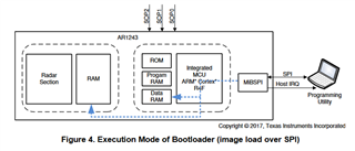
    Second (section 2.2), I can boot from the FW sent by SPI which is what I want to do. So we no longer use QSPI but SPI I/F. See Fig. 4.

    In Figure 8, the handshake is described and I see that before starting SPI transactions MSS ROM (only ROM) must boot up. So I guess no data is needed for this first part. And it seems SPI is active just after that and can receive commands given in Radar ICD.

    So it comes 2 questions that I asked you in the previous post:

    1) Is the SPI really active at this point (just after ROM)? Because with mmWaveSTUDIO if I don't load BSS and MSS I have to hostIRQ signal turning to high when I probe the signal (or does it require another SOP mode).

    2) If it is active, what is the image to load? Because we agree that only the ROM boot up performed at this point. And in the document, for programming the data flash, it is said that for AWR1243 ES3.0 we must use the metaImage. If not what is the order in which the two separated binary files must be uploaded.

    Thank you for your answer. Please can you provide me with accurate answers for my different questions. In the end I only want to do what is depicted in the Figure 4 above from your document.

    thanks a lot

  • Hi,


    The bootloader process (SOP mode) is not the same when mmWave Studio is used, so I would not use it as reference. The firmware used and bootloader flow are different with mmWave studio.


    As you can see in the mmWave Link example, in this example the SOP mode is 4


    C:\ti\mmwave_dfp_01_02_06_03\ti\example\mmwavelink_example\ mmw_example.c


    retVal = MMWL_SOPControl(deviceMap, 4);

                    if (retVal != RL_RET_CODE_OK)

                    {

                                    printf("Device map %u : SOP %d mode failed with error %d\n\n", deviceMap, 4, retVal);

                                    return -1;

                    }

                    else

                    {

                                    printf("Device map %u : SOP %d mode successful\n\n", deviceMap, 4);

                    }


    Please follow the mmwave_link example


    C:\ti\mmwave_dfp_01_02_06_03\ti\example\mmwavelink_example\ReadMe.txt


    This example loads the firmware through SPI


    Thank you

    Cesar