This thread has been locked.

If you have a related question, please click the "Ask a related question" button in the top right corner. The newly created question will be automatically linked to this question.

TMAG5110: TMAG5110B2AQDBVRQ1 functionality

Part Number: TMAG5110

No output from TMAG5110B2AQDBVRQ1. 

i am trying to evaluate TMAG5110B2AQDBVRQ1 for one of the application. 

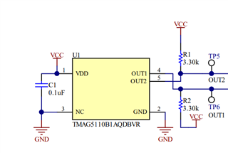
below image shows the schematic of the ckt 


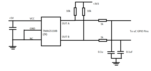
 (NC and GND Pin shorted on board)

there is a 4 pin wire harness that connect this PCB to host controller.  

i am not seeing any pulses at output. 

Magnet is able to generate more than 5mT field. Max RPM is 200. 

i am able to see pulses on A and B outputs if i use different hall sensor (ATS605LSG)

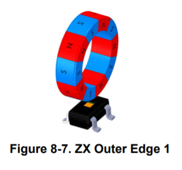
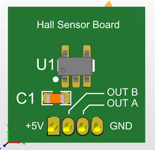
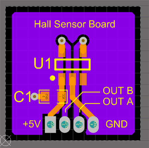
orientation of sensor is in ZX direction 


  • Abhishek,

    Thanks for reaching out with this question.  In comparison, this is the EVM schematic and Layout

    Top Copper

    Bottom Copper

    In the above example, the top copper pour is VCC while the bottom copper pour is GND.  Overall, your schematic and layout appear that they should work. The pull-up resistors are large enough that the device shouldn't be struggling to drive low.  

    I would recommend checking first that the device has a good connection on Vcc.  I would anticipate in the idle state to see about 6 mA draw.

    Another possibly useful test would be to try a few different magnet orientations to ensure that you have the sensitivity option expected.  However, even if you had the wrong orientation, I would expect to see at least one output toggle.  

    A third test you can try is to do a device swap with a second unit.  If the problem persists, then there is likely a PCB or system level problem.  If the problem is resolved, it is good practice to then re-install the original unit that was not responsive.  This will help rule out any possible soldering issues. 

    If the device continues to not work even after this ABA swap, then I would expect that it was somehow damaged during PCB assembly or application testing.  

    If both devices do not work, I would check the voltage at each pin, the supply current, and the voltage drop (if any) across the pull-up resistors and the resistors used in the output filter.  This would provide clues about any possible shorts or open conditions.

    Thanks,

    Scott