This thread has been locked.

If you have a related question, please click the "Ask a related question" button in the top right corner. The newly created question will be automatically linked to this question.

PGA300: EEPROM value change

Part Number: PGA300

Hello,

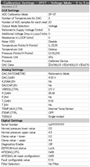
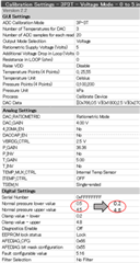
I calibrate PGA300 with EVM and GUI.

I have a problem with calibration, so I would like some advice.

Until a while ago, I was able to calibrate without problems.

When I was conducting an accuracy verification test after calibrating a sensor, the OUT voltage value suddenly became unstable.

At the end of the calibration, "successful" was displayed.

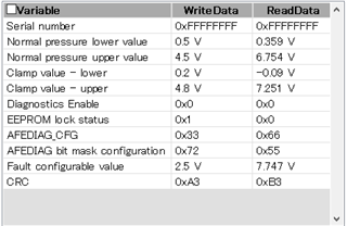
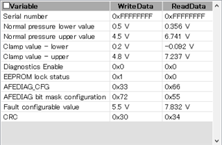
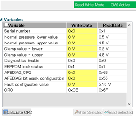
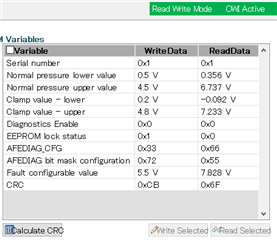
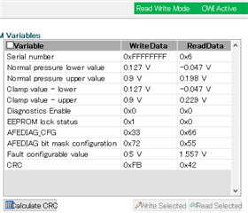
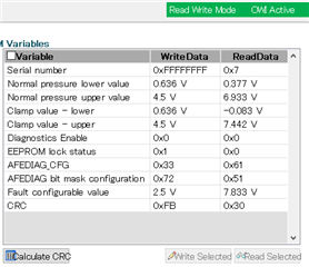
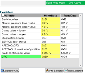
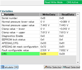
Also, when I read EEPROM Variables, there was no problem, but when I restarted the GUI, the EEPROM value changed.

EEPROM value is set to Lock.

The EEPROM value that was changing was 5, and this phenomenon is reproducible.

・Normal pressure lower / upper value

・Clamp value - lower / upper

・Fault configurable value

Since an abnormality has occurred immediately after calibration, I think that the setting at the time of calibration is a problem.

I am in great trouble, so I would appreciate any advice.

Regards,

  • Hello there,

    Have you calibrated a PGA300 and then had trouble calibrating a new PGA300?

  • Hello,

    Can you describe what happened to the output voltage? Is it getting stuck at one of the clamping values or the fault value?

    Can you show the original EEPROM map that you programmed, and then the EEPROM map that you read after it changed? 

    What are your OWI settings in the GUI?

    Regards,
    Scott

  • Hello,

    Can you describe what happened to the output voltage? Is it getting stuck at one of the clamping values or the fault value?

    Basically, I calibrate by guided calibration.

    The OUT voltage is always observed, and the OUT voltage is already unstable at the accuracy verification test after calibration.

    The OUT voltage is fluidly changing from 0.2 to 0.5V.

    Can you show the original EEPROM map that you programmed, and then the EEPROM map that you read after it changed?

    These photos are Read Data after calibration.(For Write Data, see the photo surrendered above.

    "reproducible" I said means that even with a different sensor, the value changes to a similar value as shown in the photos.

    Only the five values listed above change, and the other values don't change.

    What are your OWI settings in the GUI?

    Do "OWI settings" mean  "RLOOP" and "Additional Voltage"?

    Both of them are 0.

    Regards,

  • Hello,

    It looks like your settings should all be fine. I would start by making sure that your communication with the PGA300 is working properly. Your OWI settings are correct, but I would monitor the VDD pin referenced to the device ground during an OWI transaction. The high voltage should be around 5V, and the low voltage should be around 4V. It is also worth testing a lower baud rate (try 2400 bps). It seems like the settings you are writing may not be getting written correctly in the first place. Once it has been written to the EEPROM it will not change unless it is overwritten again.

    Next once the communication is confirmed to be working properly I would test the DAC output manually. You can do this in the DAC settings page. Just make sure that the TEST_MUX_DAC_EN bit is enabled when writing to the DAC. Make sure that the full DAC range is outputting properly.

    Regards,

    Scott

  • Hello,

    > It seems like the settings you are writing may not be getting written correctly in the first place. Once it has been written to the EEPROM it will not change unless it is overwritten again.

    I'm sorry for the lack of explanation.

    I think so, too.

    But immediately after calibration the Read Data was normal (see left photo), but when the GUI was restarted, the Read Data was changed (see right photo).

    The OUT voltage was an abnormal value immediately after calibration, and remains an abnormal value even after the GUI was restarted.

    At this time, the serial number was changed to 1 to check if the communication was normal and writing was possible.

    I reinstalled the GUI, but the result was the same.

    I try monitoring the VDD pin and lowering the baud rate once.

    Also, I try manually testing the DAC output.

    Regards,

  • Hello,

    ※ Additional information 1

    When I changed the voltage output range from 0.1V to 0.9V, the voltage was output without any problem.

    (At this time the clamp value was set from 0.1V to 1V.)

    But, when I restarted the GUI and read each value, it became an abnormal value. (see photo)

    After that, when I disconnected the communication and checked the output, the voltage output was 0.1V to 0.9V.

    ※ Additional information 2

    When I set the voltage output range from 0.5V to 4.5V, I checked the OUT voltage at 0,100,200kPa.

    As I've said before, the OUT voltage is unstable at 0Pa from 0.2V to 0.5V and eventually saturated at 0.2V. (I think that 0.2V is clamp value I set)

    However, at 100kPa, the OUT voltage is stable at about 2.5V.

    At 200kPa, the OUT voltage is unstable at about 5V.

    Also, at 0.4kPa, the OUT voltage is stable at about 0.5V.

    At 199.7kPa, the OUT voltage is stable at about 4.5V.

    At around 0kPa and 200kPa, it seems that the OUT voltage suddenly changes and is unstable.

    (see photo : I checked Read Data after calibration)

    Regards,

  • Hello,

    I tried monitoring the VDD pin and lowering the baud rate, and manually testing the DAC output.

    the VDD voltage was around 5V at high and around 4V at low.

    I changed the baud rate and calibrated, but the results did not change.

    In the DAC settings page I tested the DAC output manually, I felt that there was no problem.

    I observed the same value as when measuring the OUT voltage with Guided Calibration, but that's okay, isn't it?

    I don't know what is causing the instability.

    What causes the OUT voltage around 0kPa and 200kPa to be unstable?

    Regards,

  • Hello,

    The problem has been resolved by setting Normal pressure lower value to 0.2V and Normal pressure upper value to 4.8V.(see photo)

    The OUT voltage is stable at 0.5 ~ 4.5 V from 0 to 200 kPa.

    I have some additional questions.

    (1) Does normal pressure lower/upper value mean the lower/upper "limit" value of the output when pressure is applied?

    In that case, I guessed that the OUT voltage was unstable at 0kPa as a result of setting 0.5V at 0kPa in DAC Data and setting the lower limit to 0.5V.

    (2) What does "clamp value" mean when normal pressure lower / upper value is the lower / upper limit value?

    At first I misunderstood that "clamp value" was the lower / upper limit value.

    (3) The output is normal, and when I checked the setting value immediately after calibration, the setting value was correct. (See the left photo)

    However, when I checked the setting value after restarting the GUI, the setting value was changed. (See the right photo)

    The CRC value was recalculated before and after restarting the GUI, but the same value as at the time of calibration was calculated for both.

    What causes the setting value to change?

    Is there a problem with the setting value of normal pressure lower / upper value or clamp value?

    Regards,

  • Hello,

    Above the normal lower value, and below the normal upper value the DAC will respond based on the input and your calibration coefficients. Below the normal lower value, and above the normal upper value the DAC will be set to the lower clamping value or the upper clamping value respectively. Please refer to the Clamping section of the datasheet for more detailed descriptions.

    If you read the EEPROM data from the EEPROM read/write page, does it change in any way between the two scenarios you show in your post?

    Regards,

    Scott