I am using the EVM and have connected an AC fan as my load and running the chip with 3.3V.
I am using the A3U section but do not see any change in output.
Am I using the correct section?
This thread has been locked.
If you have a related question, please click the "Ask a related question" button in the top right corner. The newly created question will be automatically linked to this question.
I am using the EVM and have connected an AC fan as my load and running the chip with 3.3V.
I am using the A3U section but do not see any change in output.
Am I using the correct section?
Rick,
This is the unidirectional A3 variant, so you most likely want to move over to the A3B side to capture both sides of the AC signal. Operating with this device, you will get a rectified half wave as the device will only capture the positive half cycle, and will saturate during the negative half cycle. That said, you should be seeing output at least in one direction, so its odd that you aren't seeing some form of output. Is it possible to share a schematic of how you have the EVM set up, and see a scope capture of the input and output?
I've tried the A3B variant as well and got the same result with no change in output.
It's a simple setup, I have the AC line connected to the +IN terminal and the fan AC line connected to the -IN terminal.
A DC power supply for the 3.3V and a multimeter connected to the VOUT.
Rick,
Is this 1Apkpk, or 1A RMS?
There's a few things to be aware of at this current level:
First, I don't think you're completely lost in the noise, but be aware of the noise floor of the device, similar to this customer Javier helped. The noise floor for the A3 is calculated as 560mA_pkpk. You can bring this down by throttling the BW of the device from 80kHz.
Next, the expected output here for 1Apk will only be about 200mVpk, which would be reduced further for an RMS reading, which is what the DMM is going to give you. What output is showing on your DMM?
Do you have access to an oscilloscope? It may give us a better understanding of what is going on to see the actual AC waveforms, complete with the sampling integrator contribution here.
Rick,
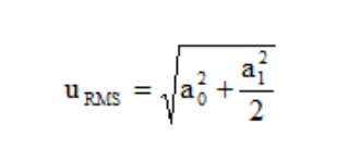
No worries. Please let me know when you've got this up and running, but this may be the issue. When you have a DC offset, the RMS value is going to be given as

So by this formula, with the 1.65V DC offset corresponding to Vs/2, the expected RMS output without signal present before addressing factors such as noise, etc. would be 1.65V, and the expected output with the signal present would be 1.656V, so the DC offset is dominating the RMS measurement, and depending on the resolution of your DMM, the actual signal may be bouncing on the LSD of the DMM.
Rick,
As I mentioned, a DMM will not be the best method to measure this. These waveforms track with the math I performed upstairs for an RMS output with offset. The scope shots demonstrate that there is a ~250mVpk output centered on 1.65V on the OUT pin when the fan is on, which with a sensitivity of 200mV/A for the A3 device corresponds to a current measured of around 1.25Apk.
For the waveforms presented above, the RMS measurements for this that the DMM will be make would be expected to be practically the same, as the theoretical ideal delta for these waveforms would be
VOUT, RMS (OFF) = sqrt(1.65^2) = 1.65V
VOUT, RMS (ON) = sqrt(1.65^2 + .250^2/2) = 1.659V
Or a total delta between the measurements of 9mV. This could easily be further complicated by noise, resolution of the DMM, etc.,