This thread has been locked.

If you have a related question, please click the "Ask a related question" button in the top right corner. The newly created question will be automatically linked to this question.

DCA1000EVM: cannot setup DCA1000

Part Number: DCA1000EVM
Other Parts Discussed in Thread: AWR1642BOOST, , AWR1642, AWR2243

We are having problem with setup DCA1000. I am using DCA1000+AWR1642BOOST and mmwave studio 2.1.1.0

It worked once well. Capturing and transferring bin file was available. However, at some point, there was a problem with the raw data transmission, and after rebooting the radar and capture board, I tried it, but it does not work well.

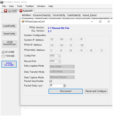
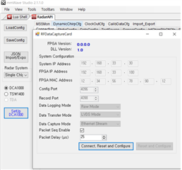
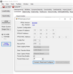
I think there is a problem with the ethernet connection. The part where the problem occurs when following the quick start menual is the last setup DCA1000EVM part, but the FPGA version cannot be read here. Even if you click Connect in the picture, it just doesn't connect without any message. When I try with the same setting, sometimes it works and sometimes it doesn't, so I think there is no problem with the IP setting or cable connection status. Also, all firewalls were allowed.

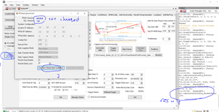
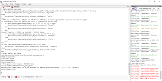
I also tried capture using a lua file to figure out the problem. The error message that occurs as a result of executing the DataCaptureDemo_xWR.lua file after connecting from the Connection section of the figure to RS232 is as follows. The red error message means "cannot fin the file name with 'cf.json'  "

I tried it with two capture boards and different 3 laptops but all didn't work. Is there any suggestion I should try? 

Or I want to know if I should buy new capture board. 

  • Hello Kyoung, 

    Apologies for the delay. 

    Have you tried some of the debug methods mentioned in the DCA1000 debugging user guide? 

    Here is the link : (+) [FAQ] DCA1000EVM: DCA1000EVM Debug Resources - Sensors forum - Sensors - TI E2E support forums 

    Please reflash the latest FPGA firmware and try again. It might've got corrupted. 

    Regards,

    Ishita

  • Thank you for your answer. 

    I have already read the above document and tried some efforts to solve the ethernet connection problem (Can not recognize the FPGA version as shown in first figure of previous thread.). These are the lists I tried.

    1. check the IP

    2. Off all the wi-fis

    3. Allow all firewall

    4. Reflash the FPGA board , we followed section 9 of the DCA1000EVM user guide. (Actually one of the capture board was able to do such job, but one of the capture  board didn't work.)

    5. Tried for 3 laptops, 2 radars,  and another MMwave studio version (2.1.1.0, 2.0.0.2)

    6. Change packet delay to 300us

    However, I still have an aforementioned trouble. Any other suggestion about the issue will be appreciated. 

    Thank you. 

  • I have update for above issue.

    Just few minutes before, I tried it with mmwavestudio 2.0.0.2 version and it worked well.

    However, it still doesn't work with mmwave studio 2.1.1.0 version.

    So actually we are able to use awr1642+dca1000evm with that version.

    However, still we cannot use awr2243+dca1000evm since ethernet connection is not available for mmwave studio 3.0.0.14 version for awr2243.

    Same problem still occurs. Is there any restriction of capture board version and mmwave version?

    thank you.

  • Hello Kyoung,

    Thankyou for your insights on this. I have a few questions, please help me understand  : 

    1. So now you're able to use AWR1642 + DCA1000 with mmWave Studio 2.0.0.2, but now 2.1.1.0, correct? 

    This is strange, since if it works with the older version, it should have worked with the latest one as well. 

    2. When using AWR2243 + DCA1000, you're not able to use mmWave Studio 3.0.0.14, correct? 

    All the issues regarding the DCA1000 functioning are usually resolved by following the debugging user guide closely.  Either the FPGA is not getting flashed properly in AWR2243, or there is some problem in ethernet connection (due to firewalls, wifi or loose cables)

    You could also send us your setup pictures and the mmWave studio log when AWR1642 worked with the older studio version. 

    Regards,

    Ishita

  • Hello Ishita, thank you for your replay.

    These are the answer for you question.

       case 1) We are able to use AWR1642+DCA1000 with mmwave studio 2.0.0.2

       case 2) We are not able to use AWR1642+DCA1000 with mmwave studio 2.1.1.0

       case 3) We are not able to use AWR2243+DCA1000 with mmwave studio 3.0.0.14

    Actually, I think we don't have any problem with wifi or firewalls or loose cables since we tried all the same setting with case 1 (using mmwavestudio 2.0.0.2). We already checked all those issues. (Also we tried to reflash FPGA board accroding to DCA1000EVM userguide)

    We attach the set up picture about above three cases. I hope it could help understanding the errors. 

    case 1) AWR1642+DCA1000 with mmwave studio 2.0.0.2 (worked well)

    case 2) AWR1642+DCA1000 with mmwave studio 2.1.1.0 (doesn't work, cannot read FPGA version and different DLL version with case 1)

    case 3) AWR2243+DCA1000 with mmwave studio 3.0.0.14 (Also doesn't work, cannot read FPGA version, same with case 2)

    Additionally, we don't have any problem with other connection settings. We only have the problem with SetupDCA1000 part related to attached pictures. 

    It will be appreciated with your apply.  

    Have a happy new year! 

    Kyoung Min.

  • Hello Kyoung Min,

    Thankyou fir your indepth insights. 

    In your Case 1 screenshot, I can see that you're using an older version of the DCA1000 FPGA firmware i.e. 2.7. 

    The latest DCA1000 FPGA firmware is 2.8. Can you reflash the FPGA with the latest firmware and try again? 

    Regards,

    Ishita

  • Hello Ishita,

    Sorry for late reply.

    Thank you for your answer and I will reply after I retry to reflash the FPGA board. 

    I have another question. Can you let me know the output unit of the AWR1642?

    In my opinion, the output unit of the raw data is uV. Is it right?

    Thank you.

    Kyoung Min.

  • Hello Kyoung Min, 

    Apologies for the delay in response at my end too. 

    If you are looking at converting the ADC code to some absolute physical value, there are two common references used:

    1) Referencing the ADC code to ADC full scale value (dBFS).

    2) Reference the ADC code to the absolute signal amplitude at Rx input pin. You can find the computation of that in the following post https://e2e.ti.com/support/sensors/f/1023/t/613223

    You can take a look at the following thread for some detailed explanation : https://e2e.ti.com/support/sensors-group/sensors/f/sensors-forum/853596/awr1642boost-dca1000-raw-data-units 

    Regards,

    Ishita