This thread has been locked.

If you have a related question, please click the "Ask a related question" button in the top right corner. The newly created question will be automatically linked to this question.

LMP91000: LMP91000 & LMP7721

Part Number: LMP91000
Other Parts Discussed in Thread: LMP7721

Hello,

I have Some Questions related 4 Electrodes Gas Sensor. Currently, I am working with  LMP91000 & LMP7721.

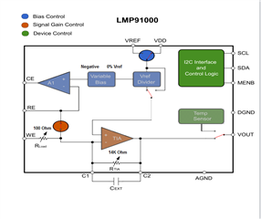
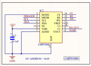
LMP91000 Configuration: ( WE,CE and RE ) 
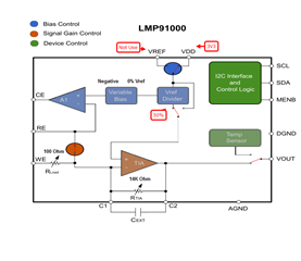
VREF DIVIDER = 50%

RTIA = 14K 

Rload = 100E 

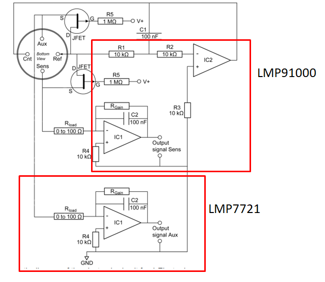
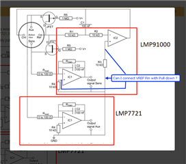
LMP7721 configuration:   Auxillary Electrode 

VREF DIVIDER = 50%

RTIA = 10K 

Rload = 100E 

Q-1) As per Josh Wyatt's suggestion, The non- inverting pin of all TIA is Pulled Down. Can I pull down the Vref Pin Externally and what happens if I select positive or negative bias? 

Q-2) Whenever LMP7721 is Restart, its Output is Reset. is it necessary for LMP7721 'ON' Continuously  (LMP91000 is always ON Condition)?  

 I  use divider at LP7721 with reference to VDD at 50%, same as LMP91000 .( Both Work on 3V3 VDD).

OCV for LMP91000 = 1.65V

OCV for LMP7721 = 1.67V

Q-3) The CO-A4 Sensor took almost 30 min for stabilizing the output. can we reduce this time using CKT? 

I am using VDD input in Voltage Divider (50%). The Output voltage is 1.65V ( OCV = Open Circuit  Voltage)  ( VDD = 3.3V ) 

Reference: https://e2e.ti.com/support/sensors-group/sensors/f/sensors-forum/831865/ccs-lmp91000-wiring-of-4-electrode-gas-sensor-with-lmp91000?tisearch=e2e-sitesearch 

Here, I attached some testing ckt conditions, Pease check,s and suggest your best solution.
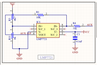
Thanks 

Sagar 

  • Sagar,

      I don't think you quite understand the intent of what you are referencing. Let me try to help you. 

    Q-1) As per Josh Wyatt's suggestion, The non- inverting pin of all TIA is Pulled Down. Can I pull down the Vref Pin Externally and what happens if I select positive or negative bias? 

    For question one, You are not pulling down VREF pin. The LMP91000 has two circuits in it. The top amplifier is creating a bias voltage to drive the probe. The bottom circuit is a transimpedance amplifier that is converting the current in the probe to a voltage. The probe develops a current based on the level of gas it measures.  

    In order to reduce power and to reduce the time to settle, you can follow the data sheet instructions "Further power savings are possible by switching off the TIA amplifier and shorting the reference electrode to the working electrode with an internal switch." this means that the bias is still applied to the probe reducing the time to start up. You are shorting the RE and WE pins of the probe together, not shorting them to ground. There is an internal switch to short the RE and CE pins together to keep the probe active and reduce current. positive or negative bias has nothing to do with low power mode. 

    Q-2) Whenever LMP7721 is Restart, its Output is Reset. is it necessary for LMP7721 'ON' Continuously  (LMP91000 is always ON Condition)?  

    The Aux pin of a 4 pin probe will provide feedback to correct the probe. This requires a second transimpedance amplifier (TIA). The LMP7721 does not have a low power or sleep mode so you can't really turn it off without creating a full startup sequence. This means that the probe will technically have to have a settling time delay.

    The LMP91000 is always on, just part of the IC the TIA is in low power mode and the probe is still active with a bias voltage. If the LMP7721 had a low power mode then you could put the second TIA in low power mode when you put the LMP91000 TIA in low power and then short RE to WE. Because the LMP7721 does not you need to keep it active which draws a few milli-amps of current all of the time.

    If you need this low power mode in your design then you need to look for a low current input amplifier that will work as a transimpedance amplifier with a low power mode.

  • Hello Sir, 

    Thanks For Your Quick Response. It is really helpful for me.

    I have some more doubts,

    1) LMP91000 use a switch like JFET for Isolate WE and RE. Currently, I am using P- channel Mosfet to Isolate AE and RE  and it is always pulled up ( Always ON).

    Is it correct for the 4th  Auxillary Electrode? 

    2) I used the same circuit used in LMP 91000. but the difference is divider connected on Non- inverting Pin of TIA. The Non-inverting pin of LMP7721  is connected pulled down as mentioned in the alpha sense 4 electrode sensor guide  ( AAN_105-03). 

    Is it good for both electrodes out[ut circuit is quite different  ( Like in Open Circuit Voltage is Difference) ? 

    3) Please suggest  Low Power Consumption TIA for future use ( Replacement of LMP7721).

    Thanks for your Valuable suggestions and Guidance.

    Thanks & Regards 

    Sagar 

  • Sagar,

    The whole purpose of shorting WE and RE in low power mode is to keep the Bias on the probe so the probe does not need a start up time. You need to research with the probe manufacture how to do this as well as how to address the AUX pin. 

    The low power mode for the LMP91000 is simple and is explained in the data sheet. The additional op-amp adds some complexity. I will move this thread to the op-amp team so that they can help you with this.

  • Hello Sir,

    Thanks for your time and guidance.