This thread has been locked.

If you have a related question, please click the "Ask a related question" button in the top right corner. The newly created question will be automatically linked to this question.

AWR1642BOOST: AWR1642BOOST

Part Number: AWR1642BOOST

I am having some trouble to configure the lab_004 of the automotive toolbox with a greater range. Using the default configuration the range is 0 to 2m, when accordingly to the calculus it should 11m like its explain in the following page: https://e2e.ti.com/support/sensors-group/sensors/f/sensors-forum/798393/faq-awr1642-maximum-range-range-resolution-in-obstacle-detection-demo.

Also, reading other discution in TI page, i realize i am not the only one with just 2m of range using the default configuration file: https://e2e.ti.com/support/sensors-group/sensors/f/sensors-forum/950255/awr1642boost-ods-how-to-configure-the-range-for-obstacle-detection-test 

I would like that someone clarify this situation  to be able to achieve a better configuration and can use this sensor in my development.

Also, i woud like to know if the configuration commands that are specific for the object detection lab affect the rest of the the commands like: profileCfg  and frameCfg .

Finally i share with you the default configuration for this lab with the specifics commands in bold:
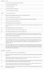
sensorStop
flushCfg
dfeDataOutputMode 1
channelCfg 15 3 0
adcCfg 2 1
adcbufCfg -1 0 0 1 1
profileCfg 0 77 7 7 58.0 0 0 67.978 1 256 5020 0 0 36
chirpCfg 0 0 0 0 0 0 0 1
chirpCfg 1 1 0 0 0 0 0 2
frameCfg 0 1 32 0 100 1 0
lowPower 0 1
guiMonitor 1 1 0 0
cfarCfg 1 4 12 4 2 8 2 350 30 2 0 5 20
dbscanCfg 4 4 13 20 3 256
sensorStart

  • Reading the documentation of the specific commands i think they shouldn't  not modify the behavior of the rest of the commands. i share with you a picture of the information given in the docs of the lab.

  • Hi,

    I recommend to start evaluating the mmWave SDK OOB demo with the AWR1642BOOST EVM.

    There is a larger variety of profile configurations provided with the SDK OOB demo. You can also use the SDK Visualizer to create a new profile configuration

    The performance of the OOB demo is similar to the lab004 demo for most use cases.

    thank you

    Cesar

  • Hi Cesar, thanks for answering. 

    Unfortunately, I'm trying yo develop an object detector algorithm to implement in an autonomous vehicle, for this reason i find so attractive the lab 004, avoiding working with the point cloud and make the develop faster. Its possible to use the firmware of this lab with a different configuration file that extends the range of the sensor? Or I'm just waiting my time and i should start working with the SDK OOB demo?.

    In case of use SDK OOB demo, can you recommend me an algorithm of clustering or a way of pass from the cloud point to the object detection?

    Regards, Joaquin

  • Hi,

    I think it is important to understand the EVM capabilities

    • AWR1642BOOST
      • This EVM has an antenna that focuses on azimuth angular resolution. So performance is better in azimuth.
      • The mmWave SDK demo can run on this board.
      • The lab004 demo does not run correctly on this board

    • AWR1642BOOST-ODS
      • This EVM was designed with an antenna that has similar performance in azimuth and elevation. So, the elevation performance for this EVM is better than the BOOST board
      • the mmWave SDK demo does not run correctly on this board
      • the lab004 demo runs on this board

    What range detection do you need for your application? Do you need to detect mostly static or moving objects?

    thank you

    Cesar

  • My application is the perception part of an autonomous vehicle, so in most of the cases there will be relative motion between the objects and the sensor. 

    My team has develop a a fusion algorithm that use detected objects as their input. For this reason, in case f choose using mmWave SDK demo, can you recommend an algorithm, a paper or something that make my able to go from point cloud to clusters? 

    Also, in my experience, the lab004 works in the AWR1642BOOST board, but with a resolution of just 2m.

  • Hi,

    What max range does the application require?

    If you want to use the lab0004 you will need to use a AWR1642BOOST-ODS board which has different antenna pattern.

    If you use the AWR1642BOOST board, you can run the demo but the angle computation, especially in elevation is not correct.

    The clustering algorithm used in lab004 demo is simple dBscan

    https://www.mathworks.com/help/stats/dbscan.html

    Thank you

    Cesar

  • My application need 30m to detect objects with enough time to stop and avoid crashes. Also, i would like to know the maximum resolution for this range of detection.

    Regards.

  • In order to understand the tradeoff between range and resolution, please see following FAQ

    https://e2e.ti.com/support/sensors-group/sensors/f/sensors-forum/1050220/faq-computing-maximum-range-velocity-and-resolution-mmwave-system

    I recommend you use the mmWave SDK OOB demo with AWR1642BOOST.

    You can start with an existing configuration and modify it for 30m range.

    Additional chirp examples are provided in the industrial toolbox chirp data base

    \mmwave_industrial_toolbox_4_8_0__all (1)\mmwave_industrial_toolbox_4_8_0\chirps

    Thank you
    Cesar