This thread has been locked.

If you have a related question, please click the "Ask a related question" button in the top right corner. The newly created question will be automatically linked to this question.

AWR1443BOOST: SPI Connect failed

Part Number: AWR1443BOOST
Other Parts Discussed in Thread: AWR1443, UNIFLASH

I have been trying to set up AWR 1443 BOOST (REV B) and DCA 1000 EVMs to capture raw data. When I click SPI Connect button, roughly after 15-20 seconds I get an error and the SPI connectivity status stays Disconnected. I followed the steps prescribed to solve this issue on the forum. Unfortunately, none of them worked for me. I need your help identifying the issue, Thank you!

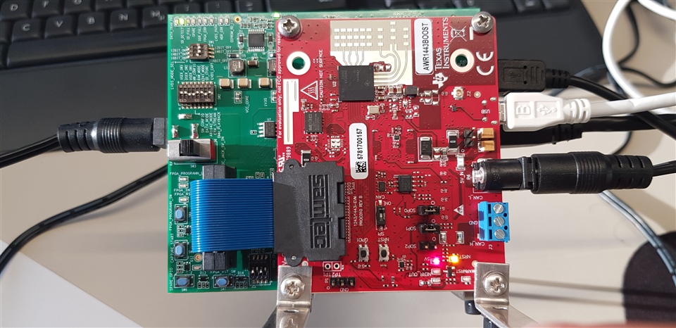
Jumpers were placed at SOP0 and SOP1 and Switch 2 were set to SPI. Power supplies for DCA and 1443 BOOST are 5V, 3A. 


  • Hi,

    The connections look correct.

    Can you please check the LVDS cable to make sure the connection is robust.

    Was this setup working before?

    Have you used the AWR1443 board with another demo?

    Thank you

    Cesar

  • Thank you for your quick response. 

    Previously, we used IWR 1443 BOOST (REV B) and DCA 1000 EVMs, and this system worked fine for us. 

    I checked, and all connections are robust. 

    I noticed that the version value is all zers(00.00.00.00 (00/00/00)) when I load the MSS FW version. This suggests I am failing to load the firmware properly. I follow another solution that can be found here on the forum. This solution suggests formatting the flash using the UNIFLASH tool. I followed the steps and formated the flash. Afterwords the problem related to the SPI connect got resolved. Afterwards, I ran into another problem, I am not sure if it is a bug or something else. 

    The default value of Sample Rate (ksps) in the mmWaveStudio is 10000. This value worked fine with IWR 1443 BOOST (REV B) and DCA 1000 EVMs, in our previous experiments. As of now we are using  AWR 1443 BOOST (REV B), this default value does not work anymore, and I get the following error.  

    I can get rid of this error if I set this value to either 5000 or 6000.

    My question is: AWR 1443 Boost and IWR 1443 Boost both are very similar devices then why the default value in the mmWave Studio is not accepted by both devices. As a consequence,  DataCaptureDemo_xWR.lua which is supposed to work on both devices does not run on AWR 1443 BOOST (REV B). 

    I also noticed that the LP Mode with a default value Regular ADC also produces the following error,


    but works fine when it is set to Low Power ADC.

    My question is: What is the difference in  Regular ADC and Low Power ADC modes? 

    I read here and here on this forum, that both IWR and AWR are similar, when it comes to RF performance. Then it is not clear to why above mentioned errors appears for AWR 1443 Boost and not for IWR 1443 Boost ?

  • Hi,

    The first thing to check would be the Rev of the AWR1443 device you have on your board.

    If it is a Rev3 device, you should see 964FC, if it is Rev2 device, you should see 964D

    Following information is accurate for Rev3:

    Based on the AWR1443 datasheet, for complex 2x mode, the max sampling rate is 12.5Msps. For complex 1x mode, the max sampling rate is 6.25Msps

    ADC Low Power mode is a mode that saves power at low Sampling Rate. I think that for AWR1443 it must always be enabled

    thank you

    Cesar

  • Hi,

    Thank you for your answer. Can you kindly guide me on where to find 964FC or 964D? I could not find these written on the EVM.

    Thank you

  • It is on the chip

    Thank you

    Cesar

  • Hi 

    Thank you for your reply, it is 964FC. ADC config was set to Complex1x thus the max sampling rate is 6.25Msps as pointed out in your answer. Whereas, Complex2x mode allows max sampling rate is 12.5Msps.

    Thank you