This thread has been locked.

If you have a related question, please click the "Ask a related question" button in the top right corner. The newly created question will be automatically linked to this question.

TMCS1107-Q1: Huge variation in measure current between sensors on different power rails

Part Number: TMCS1107-Q1
Other Parts Discussed in Thread: TMCS1107

Hi all!

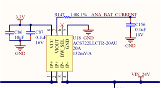
I have a legacy board that used to use ACS722 hall effect sensors, due to lack of availability, I authorized using TMCS1107A2B and updated the firmware to reflect the new sensitivity of the device (100mV/A). I was running some initial load tests and printing out measured current and it seems to be quite off on higher loads, but only for specific power rails. My sensors are working perfectly fine on 12V and 48V DC rails but for two different 24V rails, the current deviates a lot from its supposedly linear output.

My use case:

* 100mA accuracy or can be worse at loads > 10A

* Should operate at 3.3V

* DC current monitoring only


The system is running at 3.3V with 10u and 100n caps on the VS pin, and a 100n cap on the output voltage pin


24V1 readings:

Set Load (A) 3V3 at VS pin (V) Output V measured with DMM (V) Output V measured on MCU ADC (V) MCU Calculated current (A) Acceptable?
0 3.311 1.695 1.659 0.09 Yes
0.5 3.311 1.745 1.709 0.6 Yes
1 3.313 1.769 1.761 1.1 Yes
1.5 3.312 1.817 1.811 1.62 Yes
2 3.313 1.874 1.864 2.15 Yes
2.5 3.313 1.933 1.922 2.72 No
3 3.313 1.997 1.986 3.37 No
3.5 3.317 2.075 2.058 4.1 No

24V2 rail:

Set Load (A) 3V3 at VS pin (V) Output V measured with DMM (V) Output V measured on MCU ADC (V) MCU Calculated current (A) Acceptable?
0 3.312 1.724 1.661 0.1

Yes

0.5 3.312 1.776 1.712 0.62 Yes
1 3.312 1.825 1.762 1.12 Yes
1.5 3.313 1.879 1.812 1.63 Yes
2 3.313 1.932 1.865 2.15 Yes
2.5 3.314 1.983 1.924 2.73 No
3 3.314 2.055 1.988 3.37 No
3.5 3.315 2.125 2.062 4.11 No

12V rail:

Set Load (A) 3V3 at VS pin (V) Output V measured with DMM (V) Output V measured on MCU ADC (V) MCU Calculated current (A) Acceptable?
0 3.311 1.671 1.662 0.13 Yes
0.5 3.311 1.726 1.709 0.61 Yes
1 3.313 1.766 1.758 1.07 Yes
1.5 3.311 1.821 1.807 1.57 Yes
2 3.313 1.868 1.855 2.04 Yes
2.5 3.313 1.914 1.903 2.55 Yes
3 3.314 1.965 1.951 3.01 Yes
3.5 3.313 2.011 2 3.52 Yes
4 3.314 2.061 2.049 3.99 Yes
4.5 3.313 2.113 2.096 4.46 Yes
5 3.314 2.159 2.146 4.96 Yes
5.5 3.314 2.207 2.196 5.45 Yes
6 3.314 2.257 2.243 5.93 Yes
6.5 3.315 2.306 2.293 6.44 Yes
7 3.314 2.354 2.341 6.91 Yes

48V rail:

Set Load (A) 3V3 at VS pin (V) Output V measured with DMM (V) Output V measured on MCU ADC (V) MCU Calculated current (A) Acceptable?
0 3.31 1.675 1.661 0.12 Yes
0.5 3.312 1.72 1.708 0.59 Yes
1 3.315 1.771 1.756 1.06 Yes
1.5 3.315 1.822 1.807 1.57 Yes

As you can see, the output voltage for the two 24V rails deviates a lot at 2.5A+, when I increment the load by 500mA, the output voltage should increase by 50mV, but at the higher loads it increases by other increments...

The following is the equation I am using:
(ADCvoltage - VDD/2)/Sensitivity = (ADCvoltage - 1.65)/0.1

What can be done here to get a more accurate reading? I have made sure it is not just this particular board since I have seen this same trend across multiple boards with the same exact setup.

Any help would be much appreciated. Thank you!

  • Aditya,

    Thanks for using E2E!

    This is very interesting. To get started, is it possible to see the schematic and layout of your setup around the TMCS1107? Also, when running these tests, how is your test setup? Are wires connecting test points clearly away from the sensor? For an increased error over current magnitude, it may be that there is an external factor contributing error to the device. Were any other parameters changed other than the magnitude of the supply, physical or otherwise? 

    Also, in general, you may wish to check out our best practices app note located here

  • Hi Carolus!
    Following is the schematic, it does say ACS722 but we are now populating the footprint with the TMCS1107 part. The schematic is replicated across the 4 power rails:

     
    Following is the layout, I know the decoupling caps could have been placed better but being a legacy board, I am unable to change the layout


    The copper pours on pin 1 and 2 are the input current, pins 3 and 4 are output current. And the last copper pour you see flooding the chip is ground.

    As for the test setup, this is on a production board so we do not have any test points, I am probing with a DMM right on the pins of the sensor, so there may be some error due to the cable length of my probes but I doubt it would impact my readings the way it does. Testing setup and procedure was exactly the same amongst all the power rails, in fact all test were done within 2 hours, so there should be minimal environmental change. The chips were also maintained at room temperature.

    I will mention, the 24V sensors are placed exactly across switch regulators (regulators on the bottom side) so I wonder whether any switching noise if affecting these readings. Unfortunately, I do not have the equipment just yet to see if there is any noise being induced, but I doubt there is if any since the board is a 6 layer board with 2 solid ground planes in the middle which should help with induced noise.

  • Aditya,

    I find it odd that the measured data error isn't linear, and this makes me think that what is most likely occurring is external field contributions from the board itself. Are there any high current traces around the 24 rail that are not present on the 12 and 48V rails? These could potentially be adding contributions to the device. Check out section 5 of the document I attached above. Is there a way for you to test the 24V rails in isolation, without other board sections in operation? If this does prove to be the case, you may want to perform a one time board level calibration as discussed in section 6.2 of the same document to alleviate the errors showing. 

  • Carolus,

    You make some great points which line up with my thinking as well.
    I examined the layout as well and the closest high current path to one of the 24V sensors is 11mm away which is the second 24V sensor, as opposed to the 12V sensor where the closest sensor is at 30mm which is the 48V sensor. I can potentially disable other power rails and look at output of just the one 24V sensor. I appreciate your help!

  • Aditya,

    Fantastic! Please let me know if the isolation tests improve the dataset. 

  • Hi Carolus,
    Great news! I have intuitively found the cause for this issue. It is the layout, but it is not because of other nearby high current rails but the rails own regulator. I lifted the sensor in air and bodged it with wires, lifting the sensor about 2 inches off the board and my readings are now dead on!

    I am currently designing another board with the same sensor and want to be careful with layout for this particular reason. Is there any rule I can follow that should help reduce induced noise from any switching regulators? Like I know to maintain distance from switching and high current nodes, but is there any guide on the minimum distance the sensor should be at based on switching frequencies and possibly the current as well?

  • Aditya,

    Unfortunately we haven't done any characterization for nodes with switching signals, but I agree with you that isolation seems key in my opinion. Regarding current, I discuss how to calculate current trace contributions and how to refer them to the field and output of the device in section 5.2 of my app note I posted earlier in the thread. 

    Have a great weekend!