This thread has been locked.

If you have a related question, please click the "Ask a related question" button in the top right corner. The newly created question will be automatically linked to this question.

DRV5011: Hall Effect Sensors getting failed frequently

Part Number: DRV5011

Dear TI forum family,

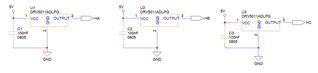
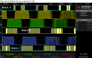
We are using Hall Effect Sensor DRV5011ADLPGM for position sensing in BLDC Hub Motors for Electric Vehicle application. But the hall sensors are getting failed frequently. 

Please do help us for understanding the cause of failure and  suggest me a good solution

Thanks in Advance.

Adarsh Raju

  • Hello Adarsh,

    Thanks for posting on the sensors forum! Can you provide some info on what kind of failure you are seeing on the sensors? And if you could also provide a schematic capture of the hall sensors portion that would be extremely helpful. Thanks, looking forward to your response!

    Best,

    Isaac

  • Dear Issac,

    Thank you for the reply. 

    When we check the non-working motors, we just found that there is no output from the hall sensors.  There is no kind of physical damage is found with them.

    Also, I have attached the schematic capture image for your reference. 

    Please help us to find a solution. 

    Adarsh Raju


  • Hello Adarsh,

    Thanks for the schematic, and for the info!

    Just a couple of other questions:

    Do all three sensors not have an output?

    Is the 5V rail for the hall sensor connected directly to the motors half bridge circuit? The concern is if the motor is coasting to a stop and generating voltage that goes beyond the device max 5.5V specification this could damage the device hence why you are not seeing an output.

    As far as the position of the hall sensors are these being placed inside the BLDC motor? Do we know how strong the magnetic field from the rotor is and the distance of the sensor? I am just curious if perhaps the sensors could be too far from the rotor and the rotor does not generate a B field strong enough to activate the latch.

    You could try testing the hall sensors by introducing a magnet close to the device if you see the output change then we know the device is functional and the problem could be the magnetic field generated by the rotor or the position of the sensors. If there is no output then the device could have been damaged in another way, perhaps not physical but electrical. Looking forward to your response!

    Best,

    Isaac

  • Dear Issac,

    No, mostly only one sensor may be failing.  Sometimes all sensors may fail. 

    5V is coming from the BLDC Drive and there is no fluctuation in the 5V supply.

    Hall Sensor is placed in the correct position. We are using magnets with a strong field and there will be less chance that it is due to the magnetic field. 

    I have attached a waveform of a BLDC Hub motor controller and Hall Sensor feedback. In most cases, hall sensor failure occurs when doing road tests.  In the dynamometer load test, they work well. 

    Thanks 

    Adarsh Raju

  • Hello- Adarsh,

    Thanks for the scope capture and the details. It looks like hall A is the only sensor you are having a problem with in this capture is staying high for some time. What is interesting is that it looks like it stays in an active high state for some time.

    Would you be able to collect how long output on hall A stays high for before the it continues as normal?

    Is this consistent from run to run when running this in your road tests or is it random?

    Have you tried swapping hall A for another DRV5011 to see if the behavior disappears with a device swap or if the problem could be present on the board?

    Best,

    Isaac

  • Hi Issac,

    Thanks for the reply.

    This scope view is taken from a working motor. 

    If the hall sensor is failed, then it is not possible to run with our motor controller.

    In addition to this, We are also facing some noise presence from the hall sensor output. 

    Could you please help us to get any noise filtration in the hall sensor output? 

    One of my suspects of the hall sensor failure is the heating of the Stator winding. Stator temperature may be reaching 100°C. 

    Is there any possibility for this too? If so, any solution to avoid this?

    Thanks,

    Adarsh Raju

  • Hello Ardash,

    Oh ok sorry I thought so the instance you sent of the scope capture the hall sensors A waveform was not working.

    Have you been able to collect an scope capture of what a non working hall sensor looks like? Does it try to pull up, is it just low the entire time?

    The device is rated for an operating temperature higher than the 100°C (either 135 or 125°C depending on the package type), so I don't think the failure is likely due to the temperature because this would also mean the other devices on the board would stop working as well.

    So far I am thinking perhaps the device you are using could be damaged, unsure of what the damage is so far or their could be a problem with the board which we could confirm if this is the case by swapping the unit on the board. Would you still be able to try a swap on a board that has a hall sensor that is not working?

    Yeah I can definitely help with a filter for the hall sensor, do you know what your max expected electrical frequency on your would be? Or the expected max speed in RPM?

  • Hi Issac,

    I'll try to get the waveform from the non-working hall sensor board. I think the voltage is low when the hall sensor is failed.  But there is a pull-up resistance on the BLDC Controller. 

    In the hall sensor board, only hall sensors are assembled. It does not contain any other components. 

    Max RPM of the motor are like to be 600-700 for Hub Motor and 2500-3000 for Inner Rotor BLDC

  • Hey Adarsh,

    Thank you, hopefully that will help us troubleshoot this issue further. The DRV5011 is a push pull output device, this means that it does not require a pull-up resistor like an open-drain device does, would you be able to try disabling the pull up resistor on the BLDC controller to see if this can help?

    Do each of these motors have a different pole count on the rotor? This will help me calculate the max electrical frequency.

    Best,

    Isaac

  • Dear Issac,

    Yes. I'll update you by removing the pull-up resistance.

    Yes, the pole pair is different. Sometime earlier, when I measured the hall frequency it was around 200-250 Hz. But I'm not sure about it. This was for an 850W Motor and Controller. 

    Thanks,

    Adarsh.

  • Hello Adarsh,

    Sorry for the delay. For the filter, typically what we see is high frequency noise so you may implement a passive low pass filter at the output of the hall sensor. At least two times the max bandwidth of your system (formula below), in your case it was observed to be around 250Hz, so the filters cutoff frequency should not go below 500Hz. I would probably recommend it to be a bit higher if possible but of course this also depends the frequency of the noise present in your system.

    Based on the information you gave me regarding the hall sensors I calculated that one of your motors should be a 10 pole motor (or 5 pole pairs) for the 3000 RPM inner rotor BLDC and the other was calculated to be around a 40 pole motor (or 20 pole pairs) for the hub motor. The hub motor pole count sounds kind of high to me so I would just verify the hall frequency of this motor or the amount of pole pairs so that you may implement the correct filter values for that motor. 

    Best,

    Isaac

  • Dear Issac,

    The Pole pair for the BLDC hub motor is 26/28 depending on the size. 

    For inner rotor is 4 pole pairs.

    I'll try to implement it and will see how the filter works. 

    Thanks

    Adarsh Raju

  • Hello Adarsh,

    Thanks for providing the pole counts on the motors.

    For the hub motor the frequency bandwidth should be ~327Hz (using 28 pole pair motor and 700 RPM) so make sure to use at least 2 times the frequency provided for your filter cutoff values.

    Inner rotor BLDC is ~200Hz (using 4 pole pairs at 3000 RPM) so the previously discussed values should work okay with this one.

    Let me know if you have any other questions!

    Best,

    Isaac

  • Dear Issac,

    Please see the attached images. Please let me know if this is sufficient for the filter at the output of the Hall Sensor. 

    Thanks, 

    Adarsh Raju

  • Hello Adarsh,

    Values look good on the hub motor output. Perhaps the inner rotor could use a lower resistor value that way the current is not too limited at the output of the device. You could probably use a 100nF capacitor and use a 3.3k resistor to get the same behavior. You could also decrease the voltage rating on the capacitors from 50V if this makes a cost difference in your device.

    Other than that it should be good!

    Best,

    Isaac

  • Hi Issac,

    Thanks for the feedback. I'll get back to you once I test the circuit. 

    Adarsh Raju

  • Thanks Adarsh, looking forward to your response!

    Best,

    Isaac

  • Hi Issac,

    Please see the following schematic.  I have designed it to test whether the hall sensors mounted on the motors are working or not. 

    Please verify and let me know the suggestions.  

    Thanks 

    Adarsh Raju

  • Hello Adarsh,

    Are the LED's being placed so that you could see the output changing on the device? If you implement this to your motor system you might not be able to see the output change since the speed at which the output changes would be too fast for our eyes to see.

    Or is this setup just being used to do a quick test on each of the hall sensors?

    Best,

    Isaac

  • Hi Issac,

    Yes. I need to check whether the hall sensor is giving output. For this usually, we rotate the motor in our hand to check. 

    Thanks,

    Adarsh Raju

  • Hello Adarsh,

    Thanks for the clarification, I just wanted to ensure you did not try to run this at speed or else you wouldnt be able to observe the LEDs. But other than that this schematic looks like it should work fine.

    Best,

    Isaac

  • Dear Issac,

    Thanks for the reply.

    What we do is just rotate the motor manually and check whether the led is blinking correctly. This will help to check the motor hall sensor easily. 

    Thank you

  • Hey Adarsh,

    Yes, if spinning manually this should not yield any problems and will allow you to check the hall sensors more easily.

    Best,

    Isaac

  • Please keep me updated on your findings, thanks!

    Best,

    Isaac

  • Hi Issac,

    Sure. I'll keep you posted.

    Thanks

  • Thanks Adarsh!

    Best,

    Isaac