Other Parts Discussed in Thread: TMP100, , TMP101-Q1
Hello, using TMP100 in a simple temp reading without using ALERT signal, we noticed in datasheet, TI recommend issuing a general call command via i2c as follow
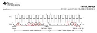
7.3.8 General Call The TMP100-Q1 and TMP101-Q1 devices respond to the I2C General Call address (0000000) if the eighth bit is 0. The device acknowledges the General Call address and responds to commands in the second byte. If the second byte is 00000100, the TMP100-Q1 and TMP101-Q1 devices latch the status of their address pins, but do not reset. If the second byte is 00000110, the TMP100-Q1 and TMP101-Q1 devices latch the status of their address pins and reset their internal registers.
7.3.10 POR (Power-On Reset) The TMP100-Q1 and TMP101-Q1 devices both have on-chip, power-on reset circuits that reset the device to default settings when the device is powered on. This circuit activates when the power supply is less than 0.3 V for more than 100 ms. If the TMP100-Q1 and TMP101-Q1 devices are powered down by removing supply voltage from the device, but the supply voltage is not assured to be less than 0.3 V, TI recommends issuing a General Call reset command on the I2C interface bus to ensure that the TMP100-Q1 and TMP101-Q1 devices are completely reset.
So there are two questions:
- sounds like general call command is a i2c write command to address 0 in frame 1 address write. and second byte with 0x06 for a reset? Then what is the purpose of writing second byte for 0x04 without a reset?
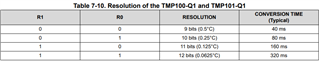
- how long should controller wait after general call command to start reading temp register?
Thanks