- Ask a related questionWhat is a related question?A related question is a question created from another question. When the related question is created, it will be automatically linked to the original question.
This thread has been locked.
If you have a related question, please click the "Ask a related question" button in the top right corner. The newly created question will be automatically linked to this question.
Could you point me towards documentation regarding the elapsed time in the radar after triggering a capture.
For example,
Essentially, we're curious how well we can approximate the "mid-point" of the exposure time, given knowledge of the trigger time. Is this feasible? As such the most interesting information for us is what happens between triggering and starting capturing.
Hello,
Please allow us until after the weekend to respond to your query.
-Shareef
Hello Morten,
Please refer to below e2e thread from this link
The delay is software programable with the granularity of 5ns upto few 10s of micro seconds.

Yes, exposure is depends on the chirp configuration.
Expected processing duration is also depends upon the chirp configuration, i.e, number of ADC samples, number chirps, number of FFT points used in range, velocity and angle estimation processing etc.
You could accurately estimate the mid point of exposure time by looking at the chirp repetition time and Hardware trigger start point time one should be able to calculate by knowing the ADC sampling rate.
Thanks and regards,
CHETHAN KUMAR Y.B.
Processing duration is applied after the exposure though right?
Meaning, the steps would be tigger -> delay -> begin capture -> finish capture -> post process -> report, right? So start of capture time is the trigger stamp + FRAME_TRIGGER_DELAY (+- 5ns) if I'm not mistaken.
Slightly unrelated: is chirp repetition time reported, or is this something to be measured over several runs? And how does ADC sampling rate play into this, if I have an idea of the chirp duration.
Morten,
Yes processing duration is considered after all the exposure or after all the chirps are transmitted.
Yes, steps are correct Trigger -> delay -> begin capture -> finish capture -> post process -> report. For hardware trigger delays are controlled, for software trigger delays are not well controlled as compared to hardware trigger.
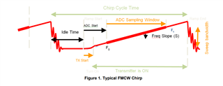
Please refer to the below timing diagram, a chirp cycle consisting of idile time, ADC start time, ADC sampling window, excess ramp time, this would be chirp cycle time.

ADC sampling need to be done on the linear region of the chirp waveform, Idle time, ADC start time need to be chosen such that ADC sampling need to be done at the linear region of the chirp waveform.
Idle time need to be incorprated so that enough time is given for the synthesizer to settle to the start frequency from the previous chirp, ADC start time is given so that ADC captured in the linear region of the chirp, There would be small non-linear region at the start of the chirp which could be avoided using ADC start time. There are trade-offs for each of these parameter. This is captured in the below app-note
https://www.ti.com/lit/an/swra553a/swra553a.pdf
If you have further questions please raise a new thread, As current thread is meant for timing information for hardware trigger. It would helpful for other customers in future.
Thanks and regards,
CHETHAN KUMAR Y.B.
Ok great. Just to confirm and conclude: if I know the timestamp of the hardware trigger, then I can calculate the mid-exposure timestamp by
TRIGGER_STAMP + TRIGGER_DELAY + (CHIRP_CYCLE_TIME * NUM_CHIRPS) / 2
where TRIGGER_DELAY is given with some ns of uncertainty, and I guess the same for the CHIRP_CYCLE_TIME.