This thread has been locked.

If you have a related question, please click the "Ask a related question" button in the top right corner. The newly created question will be automatically linked to this question.

TMP1075: How addressing works when connected to SCL or SDA

Part Number: TMP1075

Can someone please clarify how the device address config works when connectin A0 or A1 to SCL or SDA?  I see the datasheet states that the address is sampled on every bus communication, during which, the state of SCL and SDA change.  It's not clear how this works reliably on every communication, and also how this differs from connection to V+ or GND.  One thought was that it sensed a START condition, and sampled pins at that time.  However, in START condition, SDA = LOW, and SCL = HIGH....  how is it differentiated from GND and V+?   A clearer explanation would be helpful.  Thank you.

  • Hi Eric,

    Thank you for posting to the Sensing forum.

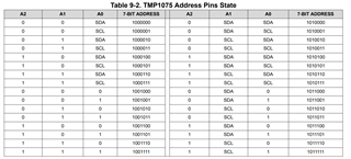
    The TMP1075 address pins are sampled on the Start condition of every transaction. Please refer to Table 9-2 in the datasheet for the 7-bit addresses that correspond with each pin state:

    Best regards,
    Nicole

  • Yes, I understand that...  my question is meant to understand HOW it differentiates SCL or SDA from simply being V+ or GND?   As I said above... In a START condition, SDA is pulled LOW while SCL is HIGH....  why aren't these simply detected as GND and V+ respectively?   Seems that the address sampling circuitry is somehow identifying the positive or negative transitions of the SCL or SDA signal during communication start to differentiate from a static voltage level.  Can you share a bit more how this actually works?

  • Hi Eric,

    The TMP1075 monitors the address pin and compares its state with SCL/SDA during the address phase of the I2C transaction. This allows the address decision to be made during the transaction. 

    Best regards,
    Nicole