This thread has been locked.

If you have a related question, please click the "Ask a related question" button in the top right corner. The newly created question will be automatically linked to this question.

DRV5056-Q1: Head on linear measurement

Part Number: DRV5056-Q1
Other Parts Discussed in Thread: TMAG5170, DRV5056, DRV5055

Hi,

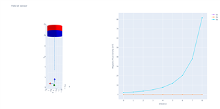
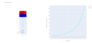
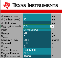
I am looking for optimal option for magnet dimensions and material(N35/N38) for below criteria.

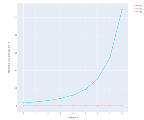
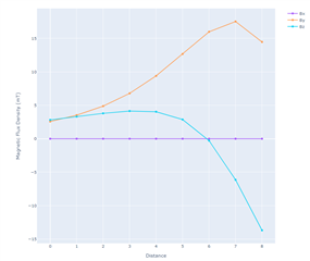
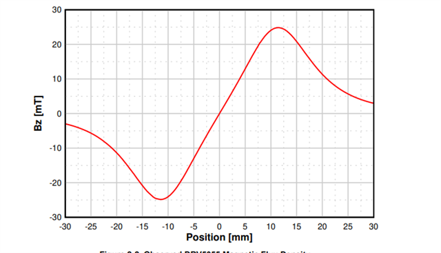
I have concern as the distance increases, the resolution is decreasing. (exponential relation)

1. Is it possible to provide the magnet dimension and material which would be optimal in size? 

2. Is it possible with low range and more sensitivity e.g DRV5055A2?

3. I am also looking for ADC to SPI chip which can handle this operation?

Thank you.

  • Hello Prathmesh,

    Thanks for posting to the sensing forum!

    You are correct there is a very exponential relationship when the device experiences a magnetic field head on. As an example I used a 3mmx3mmx3mm cube magnet with a rating of N35 as you mentioned above. I plotted the results below:

    As you can see the field is very much exponential as it gets closer to the device (indicated by the 8mm in the distance axis). 

    You could always try using a 3D device and viewing a different axis to get a more linear response. For example in this simulation I moved the device 5mm to the left of the magnet and up 2mm. If we look at the field in the Y direction we can see the field looks a bit more linear in comparison to the device getting the field directly overhead. You could always tune the placement to fine a more suitable linear range but this was meant to serve as a quick example.

    To address your questions: 

    1. Is it possible to provide the magnet dimension and material which would be optimal in size?

    I am not sure what you are trying to implement with this head on simulation and I am not aware of what your mechanical constraints are, so it is a little difficult to suggest a specific magnet. As seen in my simulations though the cube magnet rated at N35 worked great for these simulations. But again I am not sure if this is suitable for your application.

    2. Is it possible with low range and more sensitivity e.g DRV5055A2?

    If you lower the grade of the magnet then it might be necessary to move to the higher sensitivity option.

    3. I am also looking for ADC to SPI chip which can handle this operation?

    My first recommendation here would be to look at our TMAG5170 device because it seems to cover a couple of points here. This is a 3 dimensional linear hall sensor with an internal ADC and SPI output. Meaning that all the data is output through the SPI bus and you dont have to worry about interfacing with additional hardware and could simplify your board layout. There are two version depending on the magnetic range and in each one you can also configure the sensitivity on this device for different magnet types or placements.

    If you are still curious about an standalone ADC my recommendation would be to start a new thread regarding an ADC recommendation so that an engineer that services those parts can help you choose what is ideal for you.

    Best,

    Isaac

  • Thank You.

    I am looking for cylinder shape magnet only.

    Also,the 1st graph goes beyond bmax range of the sensor drv5055a3.

    The image which I posted is from the TI tool. 

    3D sensor is slower considering 85usec+roughly 800us for 32x averaging....so not going for it...

    1. Application is magnet linear displacement

    2.If we use TI tool according to the values from my image, I have concern on the values as distance increases....so what optimal dimensions  for cylindrical magnet will be good?

    How to get confidence on the values as distance increases? How can we read them with ADC? I will open new thread for ADC once I come to know whether the values at increasing distance are possible to read...

  • Hello Prathmesh,

    If your concern is the field being to large just note the device will not get damaged if you go beyond since they can handle an unlimited magnetic field. The magnetic field going above the Bmax spec on the table just indicates that the device is past the minimum linear operation region, where we don't define the outputs behavior past the linear region. Just note at these instances the output becomes saturated and clips at your 3.3V supply voltage.

    To obtain the best resolution your magnet should be sized to take advantage of most of dynamic range.

    So thank you for the clarification on what shape of magnets you were considering. I simulated an N35, 3mm diameter and 2mm thick axial cylindrical magnet using your specifications. The magnet was south facing towards the DUT and yielded the following results you see below.

    The voltage differences between a 10mm to 9mm would be about 20mV difference for the A3 version for DRV5056.

    If I simulate an N40 magnet 4.5mm diameter and 3.5mm height then it yields the following results:

    If you use the A4 version of DRV5056 then this implementation yields about a 30mV difference between 10mm and 9mm.

    I think if you have a minimum resolution for your systems farthest points that you are trying to achieve then it should be easier to size a magnet to help achieve your target resolution. Do you have a spec for your minimum resolution in this project?

    Also as a side note that a unipolar device like DRV5056 will help yield a better resolution since you have twice the voltage range to work with unlike omnipolar devices like DRV5055 which holds the quiescent voltage at half your Vcc voltage. But in order to use a unipolar device you must be able to define at production the polarity of the magnet. So if you are not able to define your polarity in production then it is better to stick to a omnipolar device.

    Best,

    Isaac

  • Thank you Isaac.

    Do you have a spec for your minimum resolution in this project?

    Resolution is 0.05mm.

    Also considering DRV5056A3 chip.

  • Hello Parthmesh,

    I don't think that such a small resolution will be possible for the farther ranges of the measurement using a head on measurement.

    I think the best approach to achieve the level of resolution you require for your system would be to use a slide by measurement approach. This option should yield a better linear behavior across most of the spectrum unlike a direct head on approach that yields a small change at large distances. Placing the sensor halfway between the magnet can yield something similar to the field below:

    If the distance range is too large then a good solution is to make an array of linear sensors like we cover in the following app note:

    https://www.ti.com/lit/an/slya051/slya051.pdf

    I hope this helps!

    Best,

    Isaac